


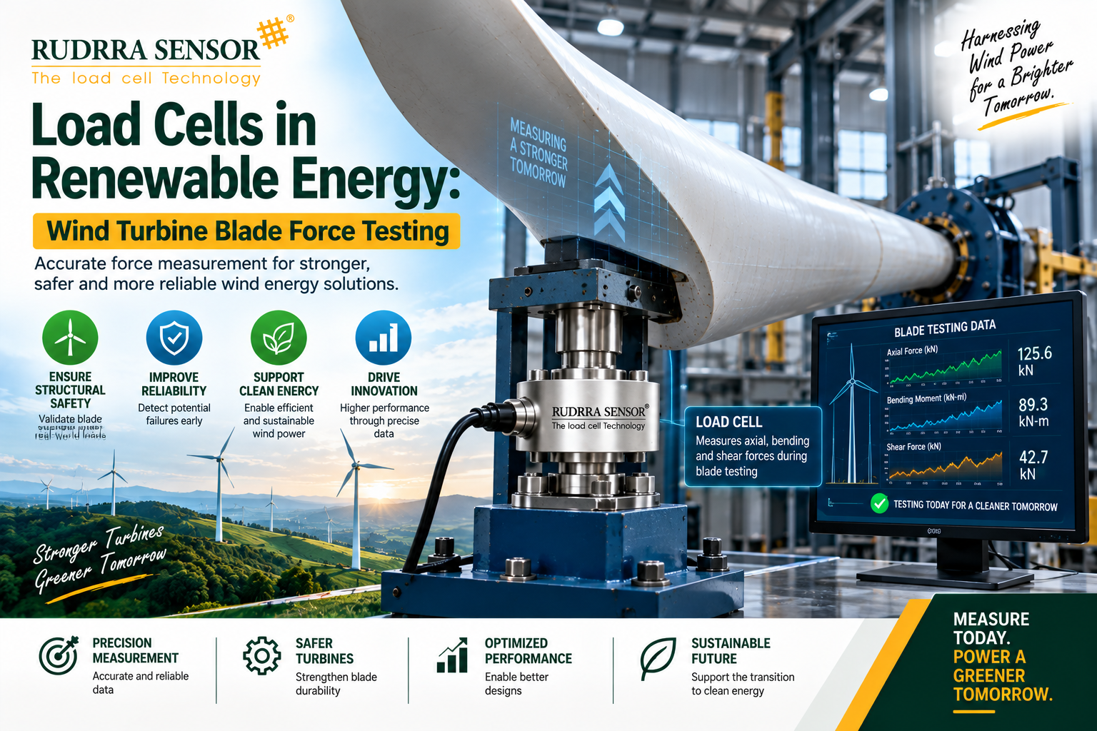
Quick answer: Wind turbine blade force testing verifies that a blade can survive decades of wind loading before it is ever installed on a tower. Load cells sit inside the hydraulic actuators and test rig fixtures that apply this loading, converting mechanical force into an electrical signal so engineers can control the exact load being applied and confirm it matches what the blade will experience in the field. Without accurate, fatigue-rated load cells, static and cyclic blade tests cannot be trusted — and a blade that passes a flawed test can fail on a live turbine years later.
That single sentence hides an enormous amount of engineering. Let’s unpack it properly.
Why This Topic Matters Right Now
Wind energy is no longer a niche renewable — it is core infrastructure. Blades keep getting longer, towers keep getting taller, and offshore installations keep pushing into rougher water. A blade built in 2015 rarely exceeded 60 metres. Today, blades crossing 100 metres are in active production, and prototype blades well beyond that are being tested for the next generation of offshore turbines. Every metre added multiplies the bending moment at the root, the fatigue cycles the structure must survive, and the cost of getting the test wrong.
A single utility-scale blade can cost anywhere from a few hundred thousand dollars to well over a million, depending on length and manufacturer. A single turbine failure caused by a blade defect that testing should have caught can run into tens of millions of dollars once you add lost generation, crane mobilisation, warranty claims, and reputational damage with the wind farm operator. This is why blade certification bodies, OEMs, and independent test labs have made force and load testing a mandatory, heavily instrumented, multi-week process rather than a formality.
This guide is written for the people who actually sit closest to that instrumentation decision — test lab engineers scoping a new rig, blade OEM instrumentation and quality teams writing procurement specifications, and technical buyers at test facilities who need to understand why one load cell quote looks nothing like another on paper, even when both claim to fit “the same job.” If that describes you, the sections ahead go well past the marketing-brochure version of this topic.
Load cells are the quiet instrument at the centre of that process. They rarely get mentioned in wind energy press releases — nobody writes a headline about a transducer — but without them, none of the load figures engineers rely on would exist. This guide walks through exactly how load cells function inside blade testing, what type of load cell fits which stage of the test campaign, the standards that shape test design, and the practical, on-the-ground problems test engineers run into when a rig is under load twenty-four hours a day for weeks at a stretch.
What Is Wind Turbine Blade Testing?
Blade testing is the structured process of applying controlled mechanical loads to a wind turbine blade to confirm it can withstand the forces it will experience across its operational life — typically 20 to 30 years — without cracking, delaminating, or failing structurally. It happens before a blade design is approved for commercial production, and it happens again periodically for quality assurance on production batches or after a design modification.
Two broad categories dominate the testing process:
- Static (ultimate) load testing — the blade is loaded, usually in flapwise and edgewise directions, up to and sometimes beyond the maximum load it is predicted to see once in its lifetime, confirming it does not fail at that extreme.
- Fatigue (cyclic) load testing — the blade is loaded repeatedly, millions of times, at a lower amplitude that simulates decades of wind gusts and rotational cycling, confirming it does not develop cracks or delamination over time.
A third, less publicised category — modal or natural frequency testing — measures how the blade vibrates and where its resonant frequencies sit, which matters enormously for the fatigue test setup itself, since resonance testing is the method most labs use to apply millions of fatigue cycles economically.
None of these tests are possible without a way to know, in real time, exactly how much force is being applied. That is the load cell’s job.
Why Blades Need This Level of Scrutiny
A wind turbine blade is, structurally, an enormous cantilevered beam rotating at the end of a rotor, subjected to gravity, aerodynamic lift and drag, gust loading, and — for the largest offshore designs — wave-induced tower motion transmitted up through the nacelle. Every rotation puts the blade root through a full stress reversal cycle. At a typical rotational speed, a blade experiences somewhere in the order of several hundred million load cycles across its design life. That is an extraordinary fatigue demand for a structure built primarily from glass or carbon fibre composite, resin, and adhesive bond lines — materials that behave very differently under repeated cyclic stress than steel does.
Failure modes engineers are specifically hunting for during testing include:
- Trailing edge cracking, often starting at adhesive bond lines between the two half-shells of the blade.
- Spar cap delamination, where the internal load-carrying laminate separates from itself under repeated bending.
- Buckling of the shell under compressive loading on the pressure side.
- Root joint failure, where the blade bolts into the hub — often the single highest-stress region on the entire structure.
- Bond line failure at shear web to spar cap interfaces.
A blade that fails any of these in the field, high up on a tower, is not a simple warranty repair. It usually means a full crane mobilisation, blade removal, and a long logistics chain to get a replacement blade to a remote site — offshore sites make this dramatically worse. This is the economic reality that makes rigorous, load-cell-instrumented testing non-negotiable rather than a checkbox exercise.
Where Load Cells Fit Inside a Blade Test Rig
A full-scale blade test rig is a substantial piece of civil and mechanical infrastructure. The blade root is bolted to a rigid steel test stand, exactly as it would bolt to the hub on a real turbine. From there, one of two loading approaches is typically used.
Actuator-based loading: Hydraulic or electromechanical actuators are attached to the blade at multiple stations along its length via saddles or straps. Each actuator applies a force in a controlled direction — usually flapwise (the direction the blade bends toward and away from the wind) and sometimes edgewise (the direction of blade rotation) — and every actuator has a load cell built into its load path, usually in-line between the actuator rod and the blade attachment point.
Resonance-based loading: For fatigue testing specifically, many labs excite the blade at or near its natural frequency using a smaller forcing mechanism — sometimes a rotating eccentric mass, sometimes a smaller servo-hydraulic actuator — so the blade essentially “swings” itself through millions of cycles with a fraction of the energy input that would be needed to force each cycle individually. Even here, a load cell at the excitation point or at the root confirms the amplitude of every cycle stays within the programmed test envelope.
In both approaches, the load cell is not a passive bystander. It sits inside a closed control loop: the test control system reads the load cell output, compares it to the target load profile for that instant, and adjusts actuator command signals accordingly, hundreds of times per second. If the load cell reading drifts, lags, or is inaccurate, the actual force on the blade drifts along with it — and the entire multi-week test result becomes unreliable.
Beyond the actuator load path, load cells (and load pins in particular) are also used at:
- Root moment measurement points, where the connection between the test rig foundation and the blade root fixture needs independent verification of applied bending moment.
- Calibration and cross-check stations, used periodically through a long test campaign to confirm the primary in-line load cells have not drifted.
- Pin joints and clevises in the loading strap system, where load pins (a load cell built into the geometry of a structural pin) measure force directly at a connection point without adding a separate in-line component.
Types of Load Cells Used in Blade Testing
Not every load cell suits this environment. Blade test rigs demand transducers that can survive continuous cyclic loading, hold calibration over weeks of unattended operation, and often sit outdoors or in semi-open test halls exposed to temperature swings, dust, and vibration. Below is how the main load cell types map onto blade test applications.
S-Type (S-Beam) Load Cells
Used inline between the actuator rod end and the strap or saddle connecting to the blade. Their tension-and-compression capability suits the alternating flapwise loading a blade experiences, and their compact geometry fits neatly into strap-and-clevis loading arrangements.
Shear Beam Load Cells
Often selected for the primary actuator load path on larger test rigs because of their high capacity range and strong performance under off-axis or side loading, which is common when a blade deflects significantly under load and pulls the actuator connection slightly off its original axis.
Load Pins
Extremely well suited to blade rigs because they replace an existing structural pin — at a clevis, shackle, or strap connection — with an instrumented version of the same pin. This means force is measured exactly where the mechanical connection exists, with no separate housing to add stack-up error or an extra failure point in the load path.
Column-Type / Compression Load Cells
Used at the base of the test stand or foundation reaction points, where large compressive forces need to be verified independent of the actuator’s own load cell — a useful cross-check for the overall force balance of the rig.
Pancake / Low-Profile Load Cells
Occasionally used in confined mounting positions where axial height is restricted, such as certain root-fixture calibration setups.
The common thread across all of these: fatigue-rated construction. A load cell chosen for blade testing must be built to survive millions of full-range loading cycles without measurable output drift — a very different demand than, say, a load cell weighing static tank contents once a day.
Full-Scale Testing vs Sub-Component Testing
Not every blade test happens on a complete, full-length blade. Two distinct testing philosophies coexist in the industry, and load cells play a somewhat different role in each.
Full-scale blade testing takes an entire manufactured blade — root to tip — and subjects it to the static and fatigue loading described throughout this guide. This is the test that ultimately supports design certification, since it captures the real structural interaction between the root, the spar, the shell, and the tip in a way no smaller test can fully replicate. It is also the most expensive and time-consuming form of testing, requiring a test hall large enough to house the entire blade and a rig capable of applying loads across its full length.
Sub-component testing isolates a specific structural feature — a section of trailing edge bond line, a spar cap laminate coupon, a root bushing and bolt arrangement — and tests it independently, often at a much smaller scale and lower cost. This approach lets engineers investigate a specific failure mode in detail, iterate on a design fix quickly, and build statistical confidence around material or joint behaviour before committing to an expensive full-scale test.
Load cells appear in both contexts, but sub-component testing often uses smaller capacity, higher-precision load cells suited to coupon-level force application, while full-scale testing demands the higher-capacity, fatigue-rated transducers discussed earlier. A well-run blade development program typically uses sub-component testing extensively during design iteration, reserving full-scale testing for design validation once the sub-component data has already de-risked the major structural decisions.
Comparing Load Cell Types for Blade Test Applications
The table below summarises how the main load cell types map onto different points in a typical blade test rig, as a quick reference for engineers scoping a new test setup.
| Load Cell Type | Typical Rig Location | Loading Direction | Why It’s Chosen |
| S-Type (S-Beam) | Actuator-to-strap connection | Tension and compression | Compact, handles alternating flapwise load well |
| Shear Beam | Primary actuator load path (large rigs) | Compression, tolerant of side load | High capacity, robust under off-axis loading as blade deflects |
| Load Pin | Clevis and strap pin joints | Shear | Measures force directly at existing structural pin, no added housing |
| Column / Compression | Foundation reaction points | Compression | Cross-checks overall rig force balance |
| Pancake / Low-Profile | Confined calibration or root-fixture positions | Compression | Fits where axial height is restricted |
This is a starting reference, not a substitute for a proper load path analysis on any specific rig — the correct choice always depends on the actual geometry, capacity, and cycling requirements of that particular test station.
Key Technical Specifications Engineers Must Verify Before Selecting a Load Cell
When a test engineer or procurement team is sourcing load cells for a blade test campaign, the datasheet review goes well beyond “what’s the capacity.” Below are the specifications that actually determine whether a load cell will hold up.
Rated Capacity and Overload Margin
The load cell must be sized so the expected test load — including any programmed overload for ultimate static tests — sits comfortably within its working range, generally somewhere in the 50–80% of rated capacity band for the peak test load, while the cell’s safe overload rating (commonly 150% of capacity or higher) provides margin against transient spikes from actuator overshoot or control system lag.
Fatigue Life Rating
This is the single most important differentiator for blade testing versus most industrial weighing applications. A load cell rated for general industrial duty may specify a fatigue life in the hundreds of thousands of cycles. Blade fatigue tests routinely run into the tens of millions of cycles over a period of weeks to months. The load cell’s fatigue rating, and the manufacturer’s test data behind that number, needs to comfortably exceed the planned test cycle count with margin.
Accuracy Class and Non-Linearity
Static ultimate load tests need high absolute accuracy at the peak load point, since a single extreme-load event determines pass or fail. Fatigue tests place more emphasis on repeatability across millions of cycles — a load cell that repeats consistently at ±0.03% of full scale across cycle four and cycle four million is more valuable than one with marginally better single-point accuracy but a tendency to creep.
Zero Drift and Creep Under Sustained Load
Static tests frequently hold peak load for an extended dwell period — sometimes minutes — to observe the blade’s response. A load cell with poor creep characteristics will show an output drift during that dwell that has nothing to do with the blade’s actual behaviour, contaminating the very data the dwell period was designed to capture.
Temperature Compensation Range
Test halls are not always climate controlled to laboratory tolerances, and outdoor test stands certainly are not. A load cell’s compensated temperature range, and its temperature effect on both zero and span, needs to match the realistic ambient swing across a test campaign that may run through more than one season.
Signal Output and Cable Robustness
Most blade rigs run mV/V analogue output into signal conditioning and DAQ hardware, though digital output load cells are increasingly used where the test control system supports it, since digital signals resist the electrical noise that a large hydraulic power unit and its associated cabling can introduce. Cable strain relief and connector sealing also matter more here than in a typical factory floor installation, because load cell cables in a blade rig are routed along a structure that is physically moving through its full deflection range on every cycle.
Side-Load and Off-Axis Tolerance
As a blade deflects under flapwise load, the geometry of the strap connecting it to the actuator changes slightly, introducing a small off-axis or moment loading component onto the load cell that a pure tension-compression application would never see. Load cells selected for this duty need documented tolerance to this kind of loading, or the rig needs mechanical joints (spherical bearings, universal joints) designed to remove it before it reaches the sensor.
Standards That Shape Blade Load Testing
Blade certification does not happen in a vacuum. International standards and classification society guidelines define how a test campaign must be structured, what safety margins apply, and what documentation a lab must produce for a blade design to receive certification. The IEC 61400 series is the most widely referenced international framework for wind turbine design and testing, with dedicated parts addressing structural design requirements and full-scale blade structural testing methodology. Classification societies and certification bodies with long histories in wind energy, including bodies that trace back to Germanischer Lloyd (GL) and DNV, publish their own guideline documents that test labs and OEMs align their rig design and load application procedures against.
For any organisation involved in supplying instrumentation into this space, the practical takeaway is straightforward: load cells and the calibration paperwork behind them need to be traceable, typically through a nationally or internationally recognised accreditation scheme, because a certification body reviewing a blade test report will want to see that the force measurement chain — actuator, load cell, signal conditioner, DAQ, calibration certificate — is demonstrably accurate and hasn’t drifted since its last calibration check.
How a Blade Test Rig Is Actually Built
Picture a test hall with a concrete strong-floor foundation rated for enormous reaction forces. The blade’s root end is bolted into a heavy steel adapter plate that itself bolts down into the strong floor, replicating exactly how the blade would bolt to a turbine hub. The blade extends out horizontally, sometimes supported at the tip end by a lightweight trolley or sling early in the setup process purely for handling, before that support is removed once the test itself begins.
Along the blade’s length, at anywhere from two to six or more stations depending on blade length and test requirements, saddle fixtures wrap around the blade’s aerodynamic shell — carefully padded and shaped so they distribute load without crushing the composite structure locally. From each saddle, a strap or rigid link runs to a hydraulic actuator mounted either overhead or to the side, depending on whether the test is applying flapwise or edgewise load at that station.
Every actuator’s load path includes an in-line load cell, wired back to signal conditioning racks and then into the test control computer. The control system runs a real-time loop: it knows the target load-versus-time profile the test plan calls for at that specific station, it reads the actual load cell output, calculates the error, and issues a corrected command to the actuator’s servo valve or drive — many times per second, continuously, for the entire test duration.
Strain gauges bonded directly onto the blade’s outer skin at critical locations — spar caps, trailing edge, root section — measure the blade’s actual structural response to the applied load, and these strain measurements are what actually get compared against the design’s predicted values. But those strain readings are only meaningful if the applied load itself, as reported by the load cells, is known with confidence. Get the load cell readings wrong, and every strain data point downstream is being compared against the wrong reference.
Static (Ultimate) Load Testing in Detail
The static test sequence typically begins with a series of proof loads at progressively increasing percentages of the design ultimate load, allowing engineers to confirm instrumentation is behaving correctly and the blade’s response tracks predictions at lower, safer load levels before committing to the full ultimate test.
At each load step, the actuators ramp load up under closed-loop control referencing the load cell signal, hold at the target load for a specified dwell period, and then ramp back down. Engineers watch strain gauge output, deflection measurements, and — increasingly — acoustic emission sensors that can detect the faint acoustic signature of micro-cracking inside the composite structure, all while the load cell confirms the applied force is exactly where the test plan says it should be.
The final static test step applies the design ultimate load, which already includes a safety factor above the maximum load the blade is predicted to see in a genuine extreme wind event across its service life. Passing this step without structural failure, and often without exceeding predicted strain values, is what allows a blade design to move forward toward certification.
Because this is a single, high-stakes load application, the accuracy of the load cell at that specific reading matters enormously. A load cell reading 2% low at the peak load step means the blade has actually only been proven to a lower ultimate load than the certification claims — a serious problem if it later needs to be relied upon in the field.
Fatigue (Cyclic) Load Testing in Detail
Fatigue testing is where the sheer volume of load cell cycling becomes the defining engineering challenge. Rather than a handful of load applications, fatigue testing subjects the blade to millions of load reversals, simulating the cumulative effect of decades of wind gusts and rotor cycling compressed into a matter of weeks or months of continuous rig operation.
Two broad fatigue test methods dominate the industry:
Forced (actuator-driven) fatigue testing applies load cycles directly through hydraulic actuators at one or more stations, with the load cell in each actuator’s load path confirming every single cycle’s peak and trough amplitude stays within the programmed tolerance band. This method offers precise control over load distribution along the blade but is energy-intensive to run continuously for the cycle counts fatigue testing requires.
Resonance testing takes advantage of the blade’s own natural frequency. A relatively small excitation force, applied at or near the blade’s resonant frequency, causes the blade to oscillate with amplitude far larger than the excitation force alone would suggest — the same principle as pushing a child on a swing at exactly the right rhythm to build large arcs from small pushes. This dramatically reduces the actuator power needed to run millions of cycles, which is why most large commercial blade fatigue tests use some form of resonance excitation. Even in this method, load cells at the excitation point and often at additional monitoring stations along the blade confirm the amplitude of every cycle, because resonance amplitude can drift if the blade’s stiffness changes slightly due to accumulating micro-damage — which is, in fact, one of the things the test is trying to detect.
Across a fatigue campaign running for weeks, load cell stability becomes the whole ballgame. A transducer with even a small zero-drift tendency, compounding cycle after cycle, will eventually report a load history that no longer matches what the blade actually experienced — undermining the test’s core purpose, which is to prove the blade can survive a known, quantified fatigue load history.
Common Challenges and Failure Points Test Engineers Actually Deal With
Anyone who has spent time around an active blade test campaign knows the load cell rarely fails in the way a textbook describes. The real-world problems tend to be more mundane and more frustrating.
Cable fatigue from continuous flexing. Load cell cables in a fatigue test rig are often routed along or near structures that move through their full range of motion millions of times. A cable that isn’t given proper strain relief and slack allowance will eventually fatigue at the connector or entry point, producing intermittent signal dropouts that look, at first glance, like a data acquisition problem rather than a cable problem.
Thermal drift across day-night cycles. A test that runs for weeks inevitably spans temperature swings, particularly in test halls without full climate control or on outdoor rigs. Load cells without adequate temperature compensation will show a subtle zero shift correlating with ambient temperature rather than blade behaviour — a pattern experienced engineers learn to recognise and rule out during data review.
Off-axis loading as blade deflection increases. As a blade bends significantly under high static load, the geometry of the strap-to-actuator connection shifts, introducing side loads onto load cells that were specified assuming pure axial loading. Rigs without spherical bearings or universal joints at these connections put unnecessary stress on the load cell and can introduce measurement error precisely at the highest, most safety-critical load steps.
Calibration verification mid-campaign. A fatigue test that runs for two or three months cannot simply trust its initial calibration blindly for the entire duration. Good test practice includes periodic cross-checks — sometimes using a secondary, independently calibrated load cell temporarily inserted into the load path — to confirm the primary instrumentation hasn’t drifted.
Connector and cable ingress in outdoor or semi-open test halls. Dust, humidity, and occasional water exposure are a real risk in test facilities that aren’t fully enclosed, making IP-rated connectors and cable glands a genuinely practical requirement rather than a datasheet formality.
Power supply noise from large hydraulic power units. The pumps and servo valves driving actuator loads draw significant electrical power and can introduce noise into nearby signal cabling. Shielded cable, proper grounding practice, and load cells with robust signal-to-noise characteristics all matter more here than in a quieter industrial weighing environment.
Mechanical fretting at pinned connections. Load pins and clevis joints subjected to millions of small oscillatory movements can develop fretting wear at the pin-to-bushing interface over an extended fatigue campaign. This is more a rig maintenance issue than a load cell specification issue, but it directly affects the accuracy of any load pin installed at that joint, and experienced rig operators build periodic joint inspection into their maintenance schedule for exactly this reason.
Human error in channel mapping. On a rig instrumented with a dozen or more load cells across multiple actuator stations, a mislabeled data acquisition channel — station four’s load cell wired into station three’s input — produces data that looks entirely plausible in isolation but silently corrupts the load history assigned to the wrong part of the blade. Rigorous commissioning checks, where each channel is individually loaded and confirmed against its expected station before the real test sequence begins, catch this before it becomes an expensive discovery weeks into a campaign.
Cost Considerations in Blade Test Instrumentation
Instrumentation cost is a small fraction of total blade test campaign cost, but it is also one of the few line items where a shortsighted decision can jeopardize the far larger investment surrounding it. A full-scale blade test campaign — including facility time, rig setup labour, actuators, data acquisition systems, and engineering analysis — commonly runs into six or seven figures depending on blade size and test scope. Against that backdrop, selecting a lower-cost load cell that lacks proper fatigue rating, or skipping a spare unit to save a modest sum, is a poor trade when weighed against the cost of a test restart or a data set that certification reviewers reject as unreliable.
A more useful way to frame the decision is total cost of ownership across the test campaign, not unit price. That includes:
- The direct cost of the load cell itself, including any amplifier or signal conditioning hardware needed alongside it.
- Calibration costs, both the initial certificate and any mid-campaign verification checks.
- The cost of rig downtime if a transducer needs replacement mid-campaign, including whatever portion of the test sequence must be repeated.
- The reputational and schedule cost if a certification body questions the reliability of the force measurement chain in a submitted test report.
Viewed this way, specifying a properly fatigue-rated, well-sealed, traceable load cell — even at a higher unit cost than a generic alternative — is almost always the more economical choice once the full campaign is considered rather than the purchase order in isolation.
A Practical Buying Guide: Selecting Load Cells for Wind Energy Test Applications
For test lab engineers, blade OEM instrumentation teams, and procurement staff sourcing load cells for this application, a structured evaluation checklist helps avoid an expensive mismatch discovered mid-campaign.
Start with the load profile, not the load cell catalogue. Define the peak static load, the fatigue amplitude and mean load, and the total planned cycle count before looking at any transducer specification sheet. This single step eliminates most sizing mistakes.
Prioritise fatigue-rated construction over marginal accuracy gains. A load cell with excellent single-point accuracy but no demonstrated fatigue rating is the wrong choice for cyclic testing, regardless of how attractive its static specification looks.
Confirm overload protection design, not just the rated overload number. Ask how the manufacturer achieves overload protection — mechanical stops built into the load cell body are generally more forgiving of an actuator overshoot event than a design relying purely on strain gauge elastic limits.
Involve the load cell supplier early, not after the rig design is finalised. Retrofitting instrumentation into a rig that was designed without input from the transducer supplier often produces awkward mounting compromises — a load cell squeezed into a bracket that was never sized for it, or a cable route that forces an unnecessarily long, noise-prone run back to the DAQ rack. Suppliers with genuine application experience in this space can usually flag these issues at the design review stage, well before steel is cut.
Match the mounting geometry to the actual rig hardware. Load pins should match existing clevis and pin dimensions precisely; S-type and shear beam cells need mounting hardware — rod ends, clevises, load buttons — specified alongside the cell itself, not sourced as an afterthought.
Verify calibration traceability and request the actual test certificate, not just a statement of compliance. For any test result that will support a certification submission, the paperwork behind the load cell’s calibration matters as much as the load cell itself.
Ask for cyclic test data, not just a fatigue rating number. A reputable manufacturer supplying instrumentation into this market should be able to describe the basis for their stated fatigue life — this is a reasonable and increasingly common question from serious test labs.
Plan for spares and redundancy. A multi-week fatigue campaign cannot afford a multi-day delay waiting for a replacement load cell. Specifying a common load cell model across multiple actuator stations, with spares held on-site, is standard practice among experienced test operators.
A Representative Test Campaign Walkthrough
To make the abstract concrete, consider how a typical mid-length utility-scale blade — somewhere in the 60 to 80 metre range — moves through a full-scale test campaign.
The blade arrives at the test facility and is bolted into the root fixture, exactly replicating its hub connection. Saddle fixtures are fitted at pre-calculated stations along the blade, and actuators are connected via straps, each with an in-line load cell wired into the data acquisition system. Before any load is applied, every load cell channel is zeroed and cross-checked against its calibration certificate, and strain gauges bonded to the blade’s surface are similarly baselined.
Static proof loading begins at low percentages of design load, ramping up in steps, with dwell periods at each level to confirm instrument stability and structural response. Assuming no anomalies, the campaign proceeds to the design ultimate load step, held for the specified dwell, then released — completing the static portion of the test.
The rig is then reconfigured, in many cases, for fatigue testing, often using resonance excitation to efficiently apply the required cycle count — frequently tens of millions of cycles — over a period that can run from several weeks to a few months of continuous or near-continuous operation. Throughout this phase, load cell data is logged continuously, with periodic human review of trends and automated alarms configured to flag any load amplitude drifting outside the programmed tolerance band.
At the conclusion of fatigue testing, the blade is typically inspected — visually, and often using non-destructive techniques like thermography or ultrasonic scanning — for any sign of developing damage, before a final residual strength static test confirms the blade retains adequate structural capacity even after its simulated fatigue life has been applied. Every load figure in the final test report, submitted to the certification body, traces back through the data acquisition chain to the load cells that measured it.
Offshore Wind: A Harder Version of the Same Problem
Offshore wind turbines push every element of blade testing further. Blades for offshore applications tend to be longer than their onshore counterparts, since larger rotors are more economically justified when foundation and installation costs are already high, and offshore wind resource is typically stronger and steadier than onshore sites. Longer blades mean higher root bending moments, larger required actuator forces, and correspondingly higher-capacity load cells throughout the test rig.
Offshore blades must also account for different load spectra in their design — wave-induced tower motion transmits some degree of additional dynamic loading up through the turbine structure, and the design load cases used to define static and fatigue test targets reflect this. From an instrumentation standpoint, this generally translates to test campaigns run at higher force levels, over longer blade spans, with correspondingly greater emphasis on load cell capacity margin and structural rigidity of the test rig itself.
The corrosive marine environment near many test and manufacturing facilities for offshore blades also raises the practical importance of load cell housing material and sealing — stainless steel construction and high IP ratings move from “nice to have” to genuinely necessary specification criteria in coastal test facilities.
Logistics compound the problem further. An onshore test facility can usually source a replacement load cell or spare part within a day or two by road. A test campaign running near a port facility supporting offshore blade manufacturing may still face longer supplier lead times than an inland industrial customer would expect, simply because fewer facilities globally are equipped to test blades at the scale offshore designs now require. This is one of the practical reasons experienced test managers hold spares on-site for every load cell model in active use on a campaign, rather than relying on the ability to source a replacement quickly if something fails mid-test.
Where the Industry Is Heading: IoT, Digital Twins, and Smarter Test Data
Blade testing has traditionally produced enormous volumes of raw data that took specialist engineers considerable time to fully analyse after a campaign concluded. That is changing. IoT-enabled load cells and digitally networked signal conditioning increasingly stream calibrated load data in real time to cloud-based or on-premises analytics platforms, allowing engineers to review load history trends, flag anomalies, and cross-check fatigue cycle counts against the test plan while the campaign is still running rather than weeks afterward.
Digital twin approaches — where a computational model of the blade is continuously updated using real test data, including load cell readings, to predict remaining fatigue life or flag developing structural changes before they become visible failures — are an active area of development across the wind energy test community. None of this is possible without a trustworthy, low-drift, well-characterised force measurement layer underneath it. The smarter the analytics, the more that intelligence depends on the fundamental accuracy of the load cell feeding it data in the first place.
Blade lengths are also continuing to grow, driven by the economics of larger rotors capturing more energy per turbine, particularly offshore. Every increase in blade length raises the bending moments and forces test rigs must apply and measure, which in turn pushes load cell manufacturers to develop higher-capacity transducers that retain the fatigue life and accuracy characteristics blade testing demands, rather than simply scaling up a design intended for static industrial weighing.
There is also a quieter, less-discussed trend worth noting: the growing use of load cell data not just to pass or fail a test, but to feed back into the design process itself. Where load history data from an earlier test campaign is compared against a new design iteration’s predicted loads, engineers can validate whether a design change actually reduced fatigue demand at the root, or whether it simply shifted the stress concentration to a different station along the blade. None of this comparative analysis is possible without confidence that the underlying load measurements, often collected months or years apart on different rigs, are consistent and traceable back to a properly maintained calibration standard.
How Rudrra Sensors Supports Wind Energy Test Applications
Rudrra Sensors manufactures load cells, load pins, amplifiers, and load indicators designed and built in India, with export supply to customers across multiple countries. For test engineering teams and blade OEMs evaluating instrumentation for renewable energy applications, several parts of the Rudrra product range map directly onto the requirements discussed throughout this guide.
S-Type load cells from the Rudrra range suit inline actuator load path applications where tension and compression measurement is needed in a compact footprint, appropriate for strap-and-clevis mounting arrangements common in blade test rigs.
Shear beam load cells in higher capacity ratings are suited to primary actuator load paths on larger test setups, where robust performance under some degree of off-axis loading is a practical necessity rather than an ideal condition.
Load pins are particularly relevant wherever a test rig already uses pin-and-clevis connections in its strap or linkage system — replacing a standard pin with an instrumented load pin measures force exactly at the connection point, without adding a separate housing into the load path.
Column-type and compression load cells suit foundation reaction point verification and cross-check stations within a test rig’s overall force balance.
Load cell amplifiers and digital indicators from Rudrra’s range support signal conditioning requirements for test rigs where long cable runs, electrical noise from hydraulic power units, or the need for a locally readable indication make amplified or digital signal transmission preferable to raw low-level mV/V output over long distances.
Every Rudrra load cell is manufactured under ISO 9001 quality management practices and supplied with calibration documentation, giving test engineering teams the traceability that certification-focused test campaigns require. For specific capacity, fatigue rating, and environmental sealing requirements tied to a particular blade test rig design, Rudrra’s engineering team works directly with customers to specify the correct product rather than pushing a generic catalogue selection into a highly specialised application.
Frequently Asked Questions (FAQs)
Q1: What is the difference between static and fatigue load testing for wind turbine blades?
Static testing applies a small number of very high loads — up to and including the design ultimate load — to confirm the blade does not fail structurally under extreme conditions. Fatigue testing applies millions of lower-amplitude cyclic loads to confirm the blade does not develop cracks or delamination over its full operational lifetime.
Q2: Why can’t strain gauges alone verify a blade test without load cells?
Strain gauges measure the blade’s structural response — how much it deforms locally under load — but that data is only meaningful when compared against a precisely known applied load. Load cells provide that independently verified force reference, closing the loop between “what force was applied” and “how did the blade respond.”
Q3: How many load cycles does a typical blade fatigue test require?
Fatigue test cycle counts vary by design life target and load spectrum, but campaigns commonly run into the tens of millions of cycles, applied over a period ranging from several weeks to a few months of continuous or near-continuous rig operation.
Q4: What capacity load cell is needed for wind turbine blade testing?
Capacity depends entirely on blade length, root bending moment, and the specific load case being tested, ranging from tens of kilonewtons on smaller sub-component tests to several hundred kilonewtons or more on full-scale tests of large utility and offshore blades. A load profile analysis should always precede load cell selection.
Q5: Can standard industrial load cells be used for blade fatigue testing?
Generally not without a specific fatigue-rated design. Standard industrial load cells are typically validated for far lower cycle counts than blade fatigue testing requires, and using an under-rated transducer risks measurement drift or premature sensor failure partway through an expensive, time-critical test campaign.
Q6: What role do load pins play in blade test rigs?
Load pins replace an existing structural pin at a clevis or strap connection with an instrumented equivalent, allowing force measurement directly at that mechanical joint without introducing a separate in-line load cell housing, which is particularly useful where space is constrained or where minimising additional joints in the load path is important.
Q7: How is load cell accuracy verified during a multi-week fatigue test?
Reputable test facilities perform periodic calibration cross-checks during long campaigns, sometimes using a secondary independently calibrated reference load cell inserted temporarily into the load path, in addition to relying on the primary instrumentation’s original calibration certificate.
Q8: Are offshore wind turbine blades tested differently from onshore blades?
The underlying test methodology — static and fatigue loading — is the same, but offshore blades tend to be longer, involve higher forces, and are designed against load spectra that account for additional dynamic effects, which generally means test rigs for offshore blades operate at higher capacities and place greater emphasis on load cell environmental sealing given the coastal or marine-adjacent facilities involved.
Q9: Do load cells used in blade testing need recalibration after the test campaign ends?
Yes. Given the cyclic stress these transducers are deliberately subjected to, most test labs recalibrate or retire load cells used in a fatigue campaign before reusing them on a subsequent test, rather than assuming a unit that has already absorbed tens of millions of cycles retains its original as-new calibration indefinitely.
A Glossary of Key Terms
Root bending moment — The bending force experienced at the point where the blade attaches to the turbine hub, generally the highest-stress location on the blade structure.
Flapwise loading — Load applied in the direction the blade bends toward and away from the oncoming wind.
Edgewise loading — Load applied in the direction of blade rotation, roughly in-plane with the rotor.
Fatigue life — The number of load cycles a component can withstand before failure or measurable performance degradation, expressed as a cycle count at a given load amplitude.
Resonance testing — A fatigue test method that excites a blade at or near its natural frequency to achieve large-amplitude cycling with relatively small excitation forces.
Design ultimate load — The maximum load a structure must survive without failure, including a safety margin above the highest load predicted during actual service.
Load pin — A structural pin instrumented internally with strain gauges, allowing it to measure the force passing through a clevis or pinned joint directly.
Overload protection — Mechanical or electrical design features in a load cell intended to prevent damage when applied force exceeds the rated capacity, often through built-in mechanical stops.
Non-linearity — The degree to which a load cell’s output deviates from a perfectly straight line relationship with applied force across its measurement range.
Zero drift — A gradual change in a load cell’s output at zero applied load, often caused by temperature variation or long-term creep in the sensing element.
Closing Thoughts
Wind turbine blade testing is, at its core, an exercise in trust — trust that a blade design bolted to a tower far offshore or on a remote hillside will keep working, unattended, for decades, through storms nobody can predict years in advance. That trust is built entirely on data, and every data point starts with a force measurement that is only as good as the load cell producing it.
It’s easy to focus attention on the size of the blade, the hydraulic power of the test rig, or the sophistication of the analytics dashboard reviewing the results. The load cell rarely gets that attention, and it rarely deserves less. Choosing the right transducer for the right point in a test rig — sized correctly, fatigue-rated appropriately, sealed against the environment it will actually operate in, and backed by traceable calibration — is one of the few decisions in this entire process where a mistake is both preventable and, if made, extremely costly to discover late.
For engineering teams building or upgrading blade test infrastructure, or for OEMs specifying instrumentation requirements for a new test campaign, that decision deserves the same rigour applied to every other part of the test plan. Rudrra Sensors works with customers across industrial and renewable energy applications to specify load cells, load pins, and signal conditioning equipment matched to the actual demands of the application — not a generic catalogue fit. Reach out to discuss the specific load profile, capacity, and environmental requirements of your next wind energy test campaign.