


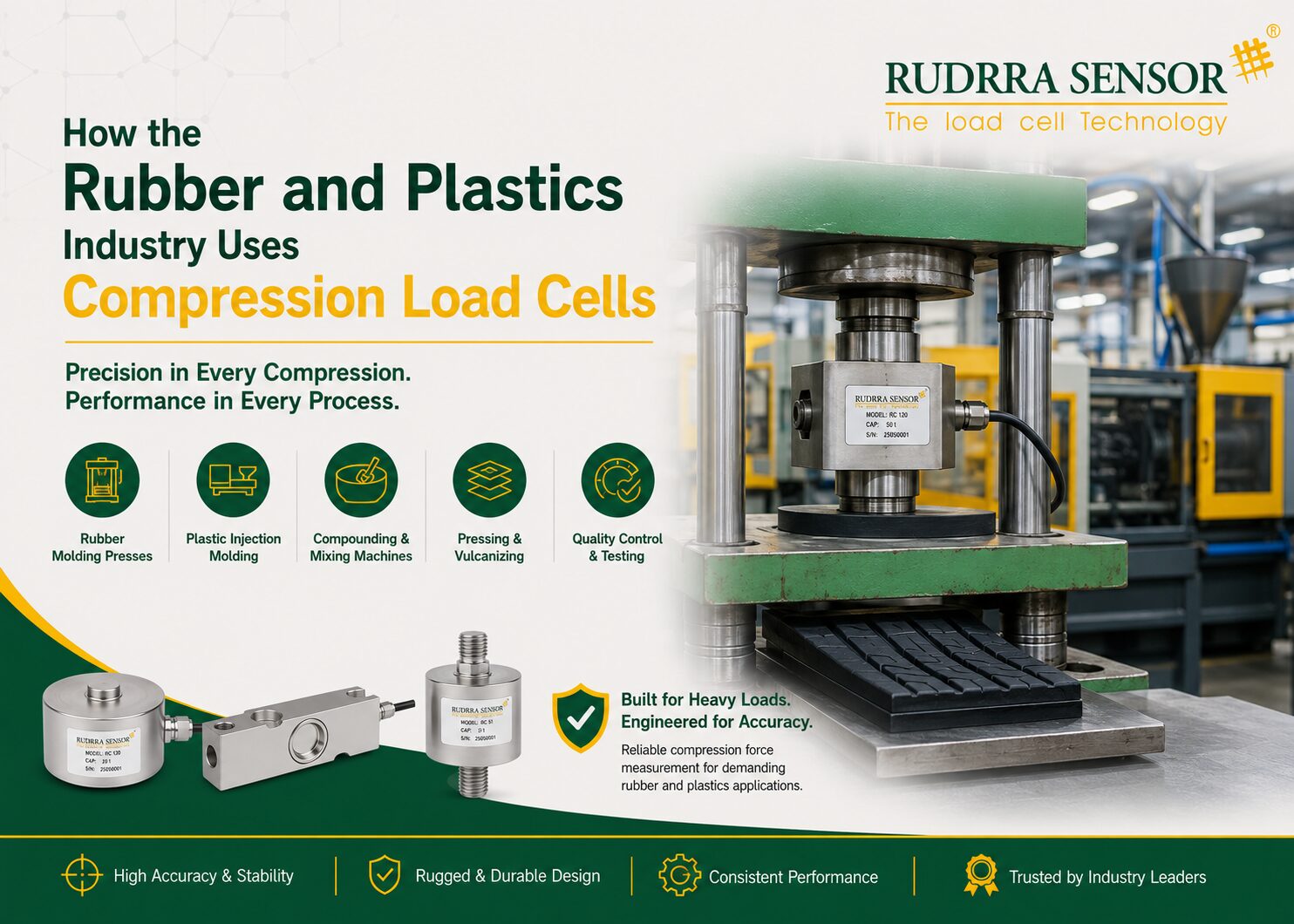
How the Rubber and Plastics Industry Uses Compression Load Cells
The rubber and plastics industry is one of the most force-intensive manufacturing sectors in the world. Whether a rubber mixing mill is blending carbon black and vulcanising agents into a natural rubber compound, an injection moulding machine is filling a precision automotive component cavity under 1,000 bar of pressure, or a hydraulic press is forming a rubber-to-metal bonded suspension bushing — the ability to measure, monitor, and control the compressive forces involved in these processes is fundamental to product quality, machine protection, and operational efficiency. Compression load cells are the primary instrument class for this force measurement, and their applications in rubber and plastics manufacturing span from the most basic batch weighing to the most demanding real-time process control.
Compression load cells — load cells that are specifically designed to measure compressive (pushing) forces applied along their sensitive axis — are the natural choice for the rubber and plastics industry for several compelling reasons. The dominant forces in this industry are compressive: injection moulding clamp force, extrusion die pressure converted to axial force, press platens squeezing rubber compounds, and calender rolls nipping rubber sheets all apply compressive loads that compression load cells measure directly and accurately. The flat, low-profile design of compression load cells (particularly the pan cake and button type designs) allows them to be integrated into press structures, mould assemblies, and machine frames with minimal modification to the equipment geometry. And the very high capacities available in compression load cells — from a few kilonewtons to tens of meganewtons — cover the extraordinary force range encountered across the rubber and plastics processing spectrum, from small laboratory presses to the largest tyre curing presses
The rubber and plastics industry also places demanding environmental requirements on its instrumentation. Processing temperatures range from ambient (cold rubber mixing) to over 200°C (thermoplastic injection moulding) to over 300°C (specialty polymer processing). Rubber compounding areas involve oils, carbon black, and vulcanising agents that attack many materials. Plastics processing areas may involve plasticisers, solvents used for mould release, and the hot vapours of processing thermoplastics. And in the tyre manufacturing segment — one of the largest and most demanding users of rubber processing equipment — the combination of high temperatures, sulphur-based vulcanising compounds, and continuous heavy-duty operation creates one of the most aggressive environments for any precision instrument.
This comprehensive guide explores all major applications of compression load cells in the rubber and plastics industry. For each application, we explain the process context, the role of compression load cells in measurement and control, the specific technical requirements arising from the processing environment and the precision demanded, and the operational benefits that compression load cell-based measurement delivers. We also provide consolidated specification guidance for the rubber and plastics sector and discuss the specific characteristics of compression load cells that make them uniquely suited to this industry.
| ₹3L Cr
India rubber & plastics industry market size |
500–1500°C
Temperature range across rubber/plastics processing |
5–50,000 kN
Force range: lab press to tyre curing press |
IP67+
Minimum IP rating for press area load cells |
The Rubber and Plastics Industry
Process overview and why compression force measurement matters everywhere
India’s Rubber and Plastics Manufacturing Sector
India is among the world’s top five producers of rubber goods and the third largest consumer of natural rubber globally. The Indian rubber industry encompasses a wide range of product segments: automotive tyres and tubes (the single largest segment, accounting for over 50% of rubber consumption), automotive components (seals, gaskets, hoses, anti-vibration mounts, and belting), industrial rubber goods (conveyor belting, rubber linings, moulded components), and consumer rubber products. The Indian plastics industry is even larger, producing over 16 million tonnes annually across injection moulded goods, extruded profiles and pipes, blown films, thermoformed products, and engineering plastics components for automotive, electronics, consumer goods, and infrastructure applications.
The economic importance of measurement accuracy in these industries is profound. In tyre manufacturing — where each passenger car tyre contains over 200 precisely measured components and must meet stringent performance and safety standards — incorrect curing press force produces tyres that fail load and endurance tests. In injection moulding of automotive structural components — engine mounts, steering components, dashboard assemblies — incorrect mould clamp force produces flash, sink marks, or internal voids that cause part rejection and costly rework. In rubber compounding, incorrect mixing of vulcanising agents produces compounds that are either under-cured (soft and weak) or over-cured (brittle and prone to cracking) in subsequent processing. Compression load cells at the right points in each of these processes are the measurement foundation that prevents these costly failures.
Why Compression Load Cells Specifically?
Of the various load cell types available — S type (tension/compression), shear beam, single point, and compression — compression load cells have become the dominant choice in rubber and plastics processing for three key reasons: first, virtually all the forces in rubber and plastics processing act in compression (pressing, clamping, forming); second, compression load cells’ flat, low-profile designs (particularly pan cake and button types) integrate seamlessly into press platens, mould cavities, and machine frames without adding mechanical complexity; and third, compression load cells are available in the very high capacity ranges (up to several MN) needed for large tyre presses and industrial moulding machines. Together, these characteristics make compression load cells the natural instrument of choice for this industry.
The Anatomy of a Compression Load Cell
Technical principles, design types, and performance characteristics
How Compression Load Cells Work
A compression load cell operates on the same fundamental principle as all strain gauge load cells: a metallic spring element deforms under the applied compressive force, and this deformation is measured by strain gauges bonded to the surface of the spring element. The spring element’s geometry is specifically designed to produce a predictable, linear deformation pattern under purely compressive loading — concentrating the strain in the areas where the strain gauges are located while maintaining structural rigidity in the other axes to minimise the effect of off-axis forces and moments.
For compression load cells, the spring element geometries most commonly used in rubber and plastics applications are the column (or canister) type and the pan cake (disc) type. In a column or canister load cell, the spring element is a hollow cylindrical column — compressive force is applied at the top and reacted at the base, and the column shortens fractionally under load. Strain gauges on the outer surface of the column measure this shortening. Canister load cells are robust, available in very high capacities (up to hundreds of tonnes), and are the standard choice for press platen monitoring, vessel support, and silo weighing in rubber and plastics plants.
Pan cake (or disc) compression load cells have an extremely flat, disc-like geometry — typically 25 to 80 mm in height for capacities up to 5,000 kN — that makes them ideal for integration into press structures, mould assemblies, and machine frames where height is constrained. The spring element is a precision-machined disc with a central bore and carefully designed stress concentration features that ensure that the strain is concentrated on the gauge bonding surfaces under pure compression. Pan cake cells are the preferred choice for press force monitoring in injection moulding, tyre curing, and rubber-to-metal bonding applications where the load cell must fit within the existing press structure.
Key Performance Characteristics for Rubber and Plastics Applications
In rubber and plastics processing applications, the following compression load cell performance parameters are most critical:
| Parameter | Definition | Typical Requirement — Rubber/Plastics |
| Rated Capacity | Maximum force for which the load cell is designed | Select 1.2–1.5× maximum expected process force; use 2× for impact/shock applications |
| Non-Linearity | Deviation of output from straight-line calibration, % RO | ≤0.05% for process control; ≤0.02% for quality-critical applications |
| Hysteresis | Difference between output on loading and unloading, % RO | ≤0.05% — important for cyclic press operations where force is applied and released repeatedly |
| Creep | Output drift over time at constant load, % RO in 30 min | ≤0.02% for mould clamping; ≤0.05% for batching applications |
| Temperature Effect on Zero | Zero shift per 10°C, % RO | ≤0.02% per 10°C — critical near heated press platens and extruder barrels |
| Natural Frequency | Load cell’s mechanical resonance frequency, Hz | Minimum 10× the highest process force variation frequency; important for dynamic press cycle monitoring |
| Safe Overload | Maximum load without permanent calibration shift | ≥150% of rated capacity — press operations involve overloads at cycle end; 300% ultimate |
| IP Rating | Sealing against dust and water ingress | IP65 minimum for dry press areas; IP67 for oily/washing environments; IP68 for outdoor |
| Material | Spring element and housing construction | Alloy steel for dry indoor press areas; 316L SS for chemical, oil, and washdown environments |
| Profile Height | Physical height of the load cell | Pan cake: 25–80 mm for press integration; canister: 80–200 mm for structural applications |
Compression vs Other Load Cell Types in Rubber/Plastics
While compression load cells dominate in the force-intensive processing applications described in this guide, other load cell types also play roles in the rubber and plastics industry:
- S type (bidirectional) load cells are used where both tension and compression may occur — for example, in die swell measurement on extruders and in some tension/compression testing machines
- Shear beam load cells are used for platform scales and batch weighing stations in compounding areas
- Single point load cells serve small weighing applications — individual ingredient weighing in laboratory compound preparations and small-volume additive dispensing
The compression load cell’s specific advantages — its ability to handle very high compressive forces in a low-profile geometry, its robust construction that survives the dynamic loading of press operations, and its availability in capacities up to the multi-MN range — make it the primary instrumentation choice for the force-intensive applications that define the rubber and plastics manufacturing process.
Detailed Application Guide — Compression Load Cells in Rubber and Plastics
Rubber and Carbon Black Batch Weighing
Controlling the most fundamental and costly raw material inputs at the start of the compounding process
Overview
Rubber compounding begins with the accurate weighing of raw materials — natural rubber (NR) or synthetic rubbers (SBR, NBR, EPDM, CR, and others), carbon black (the primary reinforcing filler, accounting for 20-35% of a typical tyre compound by weight), process oils, zinc oxide, stearic acid, antioxidants, antiozonants, accelerators, and sulphur or peroxide vulcanising agents. The precise proportioning of these ingredients according to the formulation recipe is the single most important determinant of the final rubber compound’s mechanical properties — hardness, tensile strength, tear resistance, flex fatigue resistance, and heat resistance.
Compression load cells in rubber compounding batch weighing systems are used in two configurations. First, for large-scale ingredients — rubber bales (each weighing 33-35 kg for NR, 25 kg for most synthetic rubbers), carbon black (delivered in 25 kg bags or in bulk from hoppers), and process oils (pumped from bulk tanks) — compression load cells under weighing hoppers, conveyor belt scales, and platform scales provide the accurate weight measurement needed to verify each addition against the formulation target. Second, for small-scale ingredients — accelerators, vulcanising agents, antioxidants, and other chemicals added in grams or tens of grams per 100 parts of rubber — very high-resolution compression or button load cells in precision dispensing systems measure additions to ±0.5 gram accuracy.
The accuracy of carbon black weighing is particularly important economically. Carbon black is one of the most expensive ingredients in a tyre or industrial rubber compound — it typically costs ₹70-120 per kilogram, and a typical batch may require 30-50 kg per 100 kg of rubber. A systematic over-addition of carbon black of just 1% across a large tyre plant’s daily production of 1,000 batches represents 3-5 kg of excess carbon black per batch, or 3,000-5,000 kg per day — a significant daily cost that load cell accuracy directly prevents.
Technical Considerations
- Rubber bale cutting and weighing involves heavy, awkward loads placed by forklifts or conveyor — compression load cells under the weigh hopper must have adequate dynamic overload capacity (minimum 1.5× static rated capacity) and mechanical overload stops
- Carbon black is a fine, highly dispersible powder that penetrates any unsealed gaps — compression load cells in carbon black handling areas must be IP65 minimum to prevent black infiltration into the cable entry and body seams
- Process oil weighing involves hydrocarbon oils at temperatures up to 60°C — load cells must be compatible with oil and specified for the temperature range of the heated oil system
- Small-ingredient dispensing requires very high resolution — select compression or button load cells with resolution ≥1:5,000 for any ingredient added at less than 1 kg per batch
- Vibration from carbon black pneumatic conveying must be filtered before weight readings are taken — specify indicators with digital averaging and take weight readings only when conveying has stopped
Key Benefits
- Accurate batch weighing prevents both under-formulation (which produces weak, off-specification compounds) and over-formulation (which wastes expensive ingredients without improving properties)
- Carbon black weighing accuracy directly controls one of the compound’s largest cost components — even a 0.5% accuracy improvement generates measurable annual savings in a high-volume plant
- Automated batch weighing with compression load cells reduces manual weighing errors, which are a significant source of compound batch rejection in manual dispensing operations
- Electronic batch records from load cell-based weighing systems provide traceable quality documentation required by automotive and other regulated customer specifications
Recommended Compression Load Cell Specification
For Large Ingredient Hoppers: Compression or shear beam LC × 3-4; capacity 1.3× max batch; alloy steel IP65 for dry areas; 316L SS IP67 for oil/chemical exposure
For Carbon Black Hopper: Compression × 3-4; IP65 (carbon black environment); alloy steel; vibration filter essential
For Small Ingredient Dispensing: Button or compression; high resolution (1:5,000+); capacity matched to batch size; alloy steel IP65
Output: 4-20 mA or digital to batch management system; addition cutoff integrated with PLC
Overload Protection: Mechanical stops at 120-130% rated capacity on all hopper scales
Internal Mixer (Banbury Mixer) Ram Force Monitoring
Using compression load cells to monitor and control the ram pressure in the internal mixer — the most critical machine in rubber compounding
Overview
The internal mixer (most commonly of the Banbury type, with two counter-rotating rotors in a figure-eight cross-section mixing chamber) is the most capital-intensive and most process-critical machine in any rubber compounding plant. It transforms the individually weighed ingredients into a homogeneous rubber compound through intense mechanical and thermal mixing under the pressure of a hydraulic or pneumatic floating weight (the ram) that sits above the mixing chamber and maintains a defined downward force on the compound while mixing proceeds.
The ram pressure — the force with which the floating weight presses down on the rubber compound — is one of the primary process control variables in internal mixing. Insufficient ram pressure allows the compound to climb the rotors (a condition called ‘material riding’), reducing mixing intensity and producing an inhomogeneous compound. Excessive ram pressure risks damaging the mixer seals and producing excessive heat buildup that can initiate premature vulcanisation (scorch) of the compound. The target ram pressure varies with compound formulation, mixer fill factor, and mixing stage, and must be controlled within tight limits for consistent compound quality.
Compression load cells integrated into the ram’s hydraulic cylinder assembly — or mounted between the ram drive mechanism and the floating weight structure — measure the actual downward force on the compound in real time. This direct force measurement supplements or replaces the hydraulic pressure measurement that is traditionally used to infer ram force, which is subject to friction losses and cylinder efficiency changes that make it a less accurate indicator of actual force on the compound. By measuring the actual force rather than inferring it from hydraulic pressure, compression load cells provide a more reliable and more accurate process control signal for the mixer’s automation system.
Technical Considerations
- The internal mixer environment is hot (temperatures at the mixer chamber reach 150-180°C during mixing of many compounds), dusty (carbon black dust), and oil-contaminated — compression load cells in or near the mixer must be rated for this temperature range and protected against carbon black and oil ingress
- The ram force measurement must capture both the quasi-static ram pressure during mixing and the dynamic force variations that occur as the rotors encounter material variations — specify load cells with adequate frequency response for the rotor speed (typically 20-60 RPM, giving dominant force variation frequencies of 0.3-1 Hz)
- Ram force variations occur rapidly at the start and end of each mixing phase — the load cell’s dynamic response must be adequate to capture these transitions for process monitoring purposes
- For multi-stage mixing operations, compression load cells that log the ram force profile throughout each mixing stage provide data for statistical process control — comparing the force-time profile against a reference curve to detect mixing anomalies
- ATEX certification may be required if rubber dust or process solvent vapour creates a hazardous atmosphere near the mixer
Key Benefits
- Direct force measurement at the ram provides a more accurate process control signal than hydraulic pressure inference, improving mixing consistency and compound quality
- Continuous ram force monitoring detects abnormal conditions — material riding, ram stall, mixer overload — before they cause equipment damage or compound rejection
- Ram force profile logging enables comparison between batches, providing data for statistical process control and investigation of quality deviations
- Consistent ram force control produces more uniform compound properties, reducing the variation in subsequent processing and finished product performance
Recommended Compression Load Cell Specification
Type: High-capacity compression LC (canister or pan cake); capacity 1.3× maximum ram force
Capacity Range: Typical internal mixers: 200–2,000 kN ram force; select appropriate capacity
Temperature: Extended temperature compensation to +80°C for near-mixer installation; shielded from direct heat if required
IP Rating: IP65 for carbon black environment; IP67 if oil exposure present
Frequency Response: Natural frequency ≥10 Hz for ram force dynamics; ≥100 Hz for detailed cycle analysis
Output: 4-20 mA to mixer PLC; high-speed digital for force profile logging
Rubber Calendering — Nip Force Control
Compression load cells in calender roll bearings — controlling the force that determines rubber sheet thickness and uniformity
Overview
Calendering is the process of passing rubber compound between two or more precisely heated, counter-rotating rolls to produce a uniform sheet of controlled thickness, or to apply a thin rubber coat to a fabric or wire reinforcement. Calenders are used throughout the rubber industry — in tyre manufacturing to produce the ply and belt compounds, in industrial belting to produce conveyor belt covers and breaker plies, and in coated fabric production for a wide range of flexible products.
The nip force — the compressive force between adjacent calender rolls — is the primary determinant of the rubber sheet thickness produced. For a given rubber compound at a given temperature and viscosity, the sheet thickness exiting the nip is determined by the balance between the nip force (which drives material through the gap) and the viscous resistance of the rubber (which pushes the rolls apart). If the nip force is too low, the rolls are pushed further apart by the rubber’s viscosity, producing a thicker-than-specified sheet. If it is too high, the rolls are forced together, producing a thinner sheet and risking roll damage.
Compression load cells in the calender roll bearing housings measure the actual nip force as a direct compressive load at the bearing. Each roll bearing transmits both the weight of the roll (which is a fixed known quantity) and the nip force from the adjacent roll (which varies with the rubber compound viscosity, roll speed, and roll gap setting) to the bearing housing. By measuring the total force at the bearing housing with a compression load cell, and subtracting the known roll weight, the actual nip force can be calculated in real time and used to control the roll gap adjustment system to maintain the target nip force.
Technical Considerations
- Calender rolls operate at temperatures of 60-120°C depending on the compound — compression load cells in bearing housings must be specified with temperature compensation over this range
- Calender bearing environments are heavily contaminated with rubber, oil, and rubber processing compound vapours — IP67 compression load cells with oil-resistant cable jackets are required
- The nip force measurement requires high resolution to detect small changes in nip force that correspond to the narrow acceptable thickness tolerance range of the product — specify load cells with ≥1:5,000 resolution
- Calender roll bearing loads include both static (roll weight) and dynamic (nip force) components — the load cell must be sized to handle the sum of both without saturation
- For multi-roll calenders (3-roll, 4-roll, or 5-roll configurations), independent nip force measurement at each roll pair is required — this means multiple compression load cells, one pair per nip, with individual signal conditioning
Key Benefits
- Closed-loop nip force control using compression load cell feedback produces sheet thickness variation within ±5 microns, dramatically better than the ±50-100 microns achievable with manual gap setting
- Consistent nip force across the roll width (cross-machine direction) requires independent measurement at both ends of each roll — detecting and correcting roll deflection that causes cross-machine thickness variation
- Nip force data logging enables detection of gradual changes in rubber compound viscosity (from temperature or compound variation) before they cause the sheet thickness to drift outside specification
- Automated nip force control reduces operator skill dependency and enables faster, more consistent changeovers between compounds and product specifications
Recommended Compression Load Cell Specification
Type: Compression LC (flat/pancake preferred for bearing integration); bidirectional capability if roll is also subjected to tension
Capacity: Roll weight + maximum nip force × 1.3; typical range 50–2,000 kN per bearing
Temperature: Compensated to +120°C for heated calender roll applications
IP Rating: IP67; oil-resistant PUR cable jacket
Resolution: 1:5,000 minimum for effective thickness control; higher for precision products
Configuration: One LC per bearing end; total four LCs for single-nip two-roll calender
Tyre Curing Press Force Monitoring
The most demanding compression load cell application in rubber — controlling the force that determines tyre safety and performance
Overview
Tyre curing is the final and most critical step in tyre manufacturing — the process by which the green (uncured) tyre is transformed into its finished, cross-linked form through the simultaneous application of heat and pressure in a hydraulic curing press. The curing press applies a precisely defined clamp force to the tyre mould, maintaining the mould halves firmly closed against the internal steam or hot gas pressure that inflates the tyre bladder and presses the green rubber into the mould surface. The clamp force must be sufficient to prevent the mould from opening under the internal bladder pressure, which would cause flash (excess rubber extruding through the parting line) and dimensional non-conformance of the finished tyre.
Compression load cells in tyre curing press installations serve several critical functions. The most important is measurement and verification of the actual clamp force applied to each mould. Because tyre press clamp force is generated by hydraulic pressure, it is traditionally measured by monitoring hydraulic pressure in the clamp cylinder. However, hydraulic pressure is affected by cylinder friction, seal condition, and oil temperature — making it an indirect and potentially inaccurate proxy for actual clamp force. Compression load cells mounted directly in the press structure — between the top platen and the mould, or in the press tie rods — measure the actual mechanical force applied to the mould, independent of the hydraulic system efficiency.
For large tyre manufacturing plants running multiple presses simultaneously, a compression load cell-based press monitoring system provides press-by-press performance data to the plant SCADA: which presses are running at correct clamp force, which are showing hydraulic degradation (evidenced by correct hydraulic pressure but reducing actual clamp force as seals wear), and which require maintenance. This predictive information allows the maintenance team to plan hydraulic seal replacements during scheduled downtime rather than responding to emergencies.
Technical Considerations
- Tyre curing presses operate at platen temperatures of 150-190°C and internal steam pressures of 15-25 bar — compression load cells in the press structure are subject to significant radiant and conductive heat; temperature compensation to +180°C and heat shielding are essential
- The tyre curing cycle involves a large clamp force (typically 2,000-15,000 kN depending on tyre size) applied and released every 10-30 minutes — the load cell must be rated for millions of such cycles; specify fatigue-rated load cells for continuous production presses
- Curing press environments are contaminated with mould release agent (typically silicone-based), steam condensate, and rubber flash — IP67 minimum for all load cells in the press area
- Clamp force measurement at multiple points in the press structure (e.g., at each of four tie rods) allows detection of non-uniform force distribution that can cause differential mould wear and dimensional non-conformance
- Integration with the press PLC allows automatic rejection of cure cycles where the measured clamp force falls outside specification, preventing sub-standard tyres from entering the quality test stream
Key Benefits
- Direct clamp force measurement eliminates the inaccuracy of hydraulic pressure inference, ensuring every tyre is cured at the correct force — a critical safety and quality requirement
- Hydraulic system condition monitoring through comparison of hydraulic pressure and actual clamp force enables early detection of seal wear, allowing planned maintenance before press failure
- Press-by-press force uniformity monitoring identifies equipment that is underperforming before it produces non-conformant tyres — reducing scrap and rework costs
- Long-term press force data trending supports engineering decisions about press refurbishment timing and supports claims for warranty service from press manufacturers
Recommended Compression Load Cell Specification
Type: High-capacity compression LC (canister or pancake); or load pin for tie-rod mounting
Capacity: 1.3× maximum clamp force; typical range 2,000–20,000 kN per press
Temperature: Extended temperature compensation to +180°C; heat shields between press and load cell
Fatigue Rating: Essential — specify 10M+ cycles at rated load for continuous production presses
IP Rating: IP67; silicone-resistant cable jacket; sealed cable entry
Output: 4-20 mA to press PLC; data logging for SPC and maintenance trending
Injection Moulding Clamp and Cavity Force
Compression load cells in injection moulding machine platens and mould cavities — quality at the point of production
Overview
Injection moulding is the dominant process for manufacturing precision plastic parts at high volume — from automotive structural components to consumer electronics housings, medical devices, packaging closures, and thousands of other product types. In injection moulding, a thermoplastic or thermosetting polymer is melted and injected under high pressure into a closed mould cavity, where it cools and solidifies into the shape of the cavity. The mould is held closed during filling and cooling by the machine’s clamp unit, which applies a clamping force sufficient to resist the injection pressure trying to open the mould.
Compression load cells in injection moulding machines serve two distinct measurement functions. First, in the machine’s tie bar structure: the four tie bars of a typical injection moulding machine are loaded in tension when the mould is clamped — but from the perspective of the platen structure, the force is compressive. Strain measurement in the tie bars (using strain gauge sensors bonded directly to the tie bars, or compression load cells integrated into the tie bar nut assemblies) provides a direct measurement of the actual clamping force. This measurement is used both for machine calibration (verifying that the clamp force applied matches the setpoint) and for process monitoring (detecting clamping force imbalance across the four tie bars that can cause mould distortion and part quality problems).
Second, within the mould itself: in-mould compression load cells (small button or disc type cells fitted into the mould plate) measure the actual cavity pressure at specific points inside the mould. Cavity pressure is the most direct indicator of part quality available during the moulding process — it reflects the completeness of mould filling, the effectiveness of packing, and the cooling behaviour of the melt. By monitoring cavity pressure in real time with high-resolution compression load cells, the moulding process can be controlled to produce consistent part weight, dimensions, and internal stress from shot to shot.
Technical Considerations
- In-mould compression load cells must withstand the full injection pressure — up to 1,000 bar in engineering plastics moulding — as well as the mould temperature (typically 40-120°C for thermoplastics) for millions of moulding cycles; specify fatigue-rated cells with appropriate pressure range
- Button-type compression load cells for in-mould use must fit within the mould plate without compromising the mould cooling circuit or structural integrity — minimum installation diameter constraints must be checked against cell dimensions
- Tie bar load monitoring requires cells that can withstand the aggressive tie bar clamping environment including hydraulic oil exposure, high cyclic loading, and temperature variation
- Mould cavity temperature compensation is critical — in-mould load cells are directly heated by the mould temperature controller; verify that temperature compensation covers the actual mould temperature range
- For multi-cavity moulds, in-mould load cells in each cavity provide cavity-to-cavity pressure balance data, allowing early detection of cavity-to-cavity filling imbalance that causes dimensional variation between cavities
Key Benefits
- Tie bar load balancing using compression load cell data optimises clamp force distribution, extending mould life and improving part dimensional consistency across the platen area
- In-mould cavity pressure monitoring enables 100% shot-to-shot quality control — parts produced without the correct cavity pressure profile are rejected automatically, without waiting for dimensional inspection
- Early detection of clamping force imbalance prevents the mould distortion that leads to flashing, parting line damage, and costly mould repair
- Cavity pressure data provides a process fingerprint that enables rapid diagnosis of process disturbances — identifying whether a quality deviation is caused by a material change, machine problem, or mould deterioration
Recommended Compression Load Cell Specification
Tie Bar Monitoring: Strain gauge or compression LC integrated into tie bar assembly; capacity matched to machine tonnage
In-Mould Cavity: Button compression LC; capacity up to 2,000 bar (200 MPa); fatigue-rated (10M+ cycles); diameter as small as 8-16 mm
Temperature: In-mould: compensated to +150°C minimum; tie bar: standard range typically sufficient
IP Rating: IP65 for machine area; IP67 for areas with mould cooling water or release agent spray
Fatigue: Essential for both applications — millions of moulding cycles at rated force
Output: High-speed analogue or digital for cavity pressure profile capture; 4-20 mA for clamp force monitoring
Extrusion Die Force and Melt Pressure
Compression load cells monitoring the axial force at extruder dies — protecting equipment and controlling product quality
Overview
Plastic extrusion — the continuous process of melting thermoplastic pellets and pushing the melt through a shaped die to produce profiles, pipes, sheets, films, and coatings — depends on the precise control of the melt pressure at the die inlet and the axial thrust force on the extruder screw. Both of these can be measured by compression load cells in appropriate configurations.
The axial thrust on an extruder screw — the force pushing the screw backward against the screw thrust bearing as the melt pressure in front of the screw builds up — is directly related to the melt pressure in the extruder barrel. High screw back pressure (a process variable set by the operator to achieve a certain degree of melt mixing and homogenisation) produces high axial thrust. Compression load cells integrated into the screw thrust bearing assembly measure this axial thrust in real time, providing both a measurement of actual back pressure (independent of the barrel pressure transducer) and a monitoring function for the thrust bearing condition — gradual increase in measured thrust at a given back pressure setpoint indicates bearing wear or contamination.
At the extruder die, the melt pressure drop across the die creates a net axial force on the die body. For large-diameter dies (pipe extrusion, blown film dies, sheet extrusion dies), this force can be substantial — tens of kilonewtons for large pipe dies running at high melt pressure. Compression load cells integrated into the die clamping structure measure this force, providing a real-time indicator of die resistance that can be used to detect partial die blockage (which increases die resistance), die temperature non-uniformity, and material contamination — all before they cause a visible quality problem in the extrudate.
Technical Considerations
- Extruder barrel and die temperatures range from 160°C (commodity polyolefins) to 320°C (high-temperature engineering polymers) — compression load cells in or adjacent to the extruder must be rated for these temperatures, with thermal shields between the extruder body and the load cell where necessary
- Screw thrust bearing environments are contaminated with high-temperature polymer melt, lubricating oil, and metal wear particles — IP67 and oil-resistant materials are required
- The axial thrust measurement on a twin-screw extruder is more complex than on a single-screw machine — each screw has its own thrust bearing, and the load cells must be arranged to measure the net thrust of both screws’ combined contribution to back pressure
- Dynamic force variations at the die (from screw pulsation, gear pump variations, and material inhomogeneity) require adequate load cell frequency response — specify natural frequency ≥50 Hz for detailed process monitoring
- For underwater pelletiser die systems, compression load cells measuring the die plate clamping force ensure that the die plate is held correctly against the cutter hub under the process pressure
Key Benefits
- Screw thrust monitoring provides early warning of extruder screw and barrel wear, allowing planned maintenance before catastrophic equipment failure
- Die resistance monitoring detects partial blockage — caused by degraded material, contamination, or die land erosion — before it causes visible quality problems in the extrudate
- Measurement of actual axial thrust provides an independent validation of barrel pressure transmitter readings, improving process control reliability
- For dies with heated or cooled segments (lip heaters, die body heaters), compression load cell data enables identification of thermal non-uniformity affecting die flow distribution
Recommended Compression Load Cell Specification
Screw Thrust Bearing: Compression LC (canister or pan cake); capacity 1.3× max screw thrust; extended temperature range
Die Force Monitoring: Compression LC × 3-4 in die clamp structure; capacity matched to die force; IP67
Temperature: Compensated to +200°C for general plastic extrusion; to +320°C for high-temperature polymers with heat shields
IP Rating: IP67; high-temperature cable to die area; standard cable for thrust bearing area
Frequency Response: ≥50 Hz for detailed process dynamics monitoring
Output: 4-20 mA to extruder control system; high-speed digital for process analysis
Blow Moulding and Thermoforming
Compression load cells monitoring clamp force and forming pressure in blown and thermoformed packaging and industrial parts
Overview
Blow moulding and thermoforming are two of the most widely used processes for producing plastic containers, packaging, and hollow industrial components. In blow moulding — used to produce bottles, containers, and technical hollow parts — a parison (hollow tube) of molten plastic is enclosed in a closed mould and inflated with compressed air until it conforms to the mould cavity shape. In thermoforming — used to produce packaging trays, cups, blister packs, automotive interior panels, and similar products — a heated sheet of thermoplastic is formed over or into a mould by the application of vacuum, pressure, or mechanical force.
In both processes, the mould clamping force is a critical parameter that determines part quality, flash formation, and mould life. Compression load cells in the platen or clamping mechanism of blow moulding machines measure the actual clamp force applied to the mould, providing the machine control system with direct force feedback rather than relying on hydraulic pressure inference. This is particularly important in high-volume blow moulding operations — PET bottle production lines running at 20,000-30,000 bottles per hour, for example — where consistent clamp force is essential for dimensional consistency of the finished bottle.
In thermoforming, compression load cells in the press platen measure the forming force applied to the plastic sheet, providing real-time monitoring of the process that detects variations in sheet temperature (which affect formability and required forming force), sheet thickness, and tooling condition. For matched metal die thermoforming of technical parts (automotive door panels, under-bonnet components), where forming force control is as important as in rubber moulding, compression load cells enable the same level of process control that is standard in metal forming operations.
Technical Considerations
- Blow moulding temperatures (mould temperature typically 10-30°C; parison temperature 200-280°C) create a significant temperature gradient near the load cell — standard temperature compensation is usually sufficient for mould-mounted cells, but confirm the actual installation temperature
- Mould cooling water, compressed air leakage, and mould release agents create a wet, contaminated environment — IP67 for all blow moulding machine load cells
- High-cycle blow moulding machines (20,000+ cycles/hour) impose extreme fatigue loading on in-mould components — compression load cells in high-speed blow moulding must be fatigue-rated for many millions of cycles
- For multi-layer co-extrusion blow moulding, the parison weight consistency is also monitored using load cells on the parison extrusion head — though this is typically an S type rather than compression application
- Thermoforming forming force requirements are lower than injection moulding or rubber pressing — compression load cells with lower capacities (10-500 kN range) and higher resolution are appropriate
Key Benefits
- Clamp force monitoring in blow moulding ensures consistent part wall thickness and dimensional accuracy — particularly critical for carbonated beverage bottles where dimensional tolerance determines performance on high-speed filling lines
- Detection of abnormal clamp force at individual cavity positions in multi-cavity blow moulds identifies cavity-specific tooling problems before they produce out-of-tolerance parts
- Thermoforming force monitoring enables closed-loop control of forming pressure, producing more consistent formed parts with less sheet material variation and fewer scrap parts
- Preventive detection of clamp mechanism wear through force monitoring trends reduces the risk of catastrophic clamp failure during production
Recommended Compression Load Cell Specification
Blow Moulding Clamp: Compression LC; capacity 1.3× max clamp force; fatigue-rated; IP67
Thermoforming Press: Compression LC × 4; capacity matched to forming force; IP65 minimum; IP67 with release agent
Capacity Range: Blow moulding: 100 kN – 5,000 kN; thermoforming: 10 kN – 2,000 kN
Fatigue Rating: High-speed blow moulding: essential (millions of cycles); thermoforming: standard fatigue rating sufficient
Temperature: Standard range typically adequate; verify mould-area ambient temperature at installation location
Output: 4-20 mA to machine PLC; alarming on deviation from setpoint
Hydraulic Press Force Monitoring — Rubber-to-Metal Bonding
Precision compression load cells in bonding presses — where rubber meets metal in safety-critical automotive components
Overview
Rubber-to-metal bonded components — engine mounts, suspension bushings, anti-vibration mounts, gearbox mounts, and dozens of other automotive and industrial components — are manufactured by moulding rubber directly onto a metal insert in a hydraulic or mechanical press. The rubber is bonded to the metal by a combination of heat, pressure, and adhesive (either applied to the metal before moulding or generated in situ by the vulcanisation chemistry). The quality of the bond — its strength, uniformity, and durability — depends critically on the accuracy and consistency of the press force and temperature applied during the moulding cycle.
Compression load cells in the press structure of rubber-to-metal bonding presses measure the actual forming force applied to each mould. This measurement is essential for two reasons. First, quality assurance: automotive specifications for rubber-to-metal bonded components (supplied under IATF 16949 or equivalent quality standards) require that every component is produced within defined process parameter limits, including press force. A component moulded at insufficient force has an incompletely formed rubber profile and a potentially weak bond — a safety concern in a vehicle suspension component. Second, process optimisation: the relationship between press force and bond quality is compound- and geometry-specific; compression load cell data from development and production runs provides the empirical data needed to optimise the process parameters for each new component.
In large automotive rubber component plants producing millions of bushings and mounts per year on hundreds of presses, a compression load cell monitoring system on every press provides the statistical data for process capability analysis (Cp and Cpk) required by automotive quality standards. Each press’s force data is logged against the production time and batch identity, creating a complete quality record that supports customer audits, warranty claim investigation, and continuous improvement activities.
Technical Considerations
- Bonding press temperatures (mould temperature 150-180°C for most rubber compounds) require compression load cells with extended temperature compensation — and thermal shielding from the heated platens if direct contact mounting is used
- Rubber flash and adhesive contamination in the press area can accumulate on load cell surfaces — regular cleaning is required; IP65 minimum to prevent ingress into the cell body
- Multi-platen pressing (multiple mould sets in a single press) requires compression load cells at each platen level for independent force monitoring at each stage
- Hydraulic press force variation due to seal wear or oil temperature change must be detectable by the load cell — specify resolution of ≤0.1% of rated capacity for effective process control
- For IATF 16949 compliance, compression load cell calibration records must be maintained with NABL-traceable test weight certificates; calibration interval typically annual or per customer requirement
Key Benefits
- Direct press force measurement ensures that every component is produced within the specified force window, providing the process control evidence required by automotive quality standards
- Detection of press force drift (from hydraulic seal wear or oil temperature changes) allows planned maintenance before the force drifts outside specification — preventing the rejection of components produced at out-of-specification force
- Force data logging for every component supports full traceability required by automotive customers — critical for warranty claim investigation and regulatory compliance
- Statistical process control using Cp and Cpk analysis of press force data provides evidence of process capability for IATF 16949 customer audits
Recommended Compression Load Cell Specification
Type: Pan cake (disc) compression LC; capacity 1.3× max press force; low profile for platen integration
Capacity Range: Rubber-to-metal presses: 100 kN – 10,000 kN depending on component size
Temperature: Extended temperature compensation to +180°C; thermal shield between heated platen and load cell
IP Rating: IP65 minimum; IP67 if mould cooling water or release agent spray present
Calibration: NABL-traceable; OIML C3 for IATF 16949 requirements; annual recalibration minimum
Output: 4-20 mA to press PLC; data logging to quality management system for Cp/Cpk analysis
Rubber Compound and Polymer Batch Weighing — High-Accuracy Dispensing
Compression load cells in high-accuracy chemical dispensing systems for specialty rubber and engineering plastic compounding
Overview
Beyond the large-scale ingredient weighing covered in Application 1, the rubber and plastics compounding industry includes a wide range of high-accuracy, small-quantity dispensing applications where the accuracy requirements are more demanding and the ingredient values are higher. These applications include: dispensing of specialty accelerators and vulcanisation agents in natural and synthetic rubber compounding; weighing of colour masterbatches and UV stabilisers in plastics compounding; addition of flame retardants, impact modifiers, and nucleating agents in engineering plastics; and measurement of catalyst and co-catalyst additions in specialty polymer synthesis.
In each of these applications, the quantity added is small (grams to hundreds of grams per batch) but the impact on final properties is large. A sulphenamide accelerator added at 1 part per hundred rubber (phr) in a natural rubber compound — approximately 10 grams per kilogram of rubber — controls the onset of vulcanisation. Too little, and the compound vulcanises slowly, reducing productivity; too much, and it scorches during processing or produces an over-cured compound with reduced mechanical properties. The accuracy required for these additions is ±0.5 to ±2 grams per batch — achievable only with high-resolution compression load cells.
For specialty polymer compounding — where engineering plastics such as polyamide (nylon), polycarbonate, PEEK, and thermoplastic elastomers are compounded with precisely controlled levels of glass fibre, mineral filler, impact modifiers, and heat stabilisers — the accuracy requirements are similarly demanding. Glass fibre content, for example, must typically be controlled to ±0.5% by weight of the total compound to meet the customer’s mechanical property specifications. In a 100 kg batch, this means weighing the glass fibre addition to ±500 grams — achievable with a compression load cell system with a full-scale capacity of 5,000 kg and a resolution of 500 grams.
Technical Considerations
- Very high-resolution compression or button load cells required — specify 1:10,000 resolution for additions below 100 grams per batch
- Electrostatic charging of rubber chemicals and plastic powders can cause particles to adhere to or fall from load cell surfaces erratically — earthing of the weighing system and anti-static measures are important in powder dispensing areas
- Rubber chemical areas may have specific chemical compatibility requirements — sulphur compounds, accelerators, and peroxides have varying chemical aggressiveness; verify compatibility with the specific chemicals in use
- Dispensing accuracy is affected by residual material in the hopper (carryover) after the addition cutoff — use load cells with fast settling time and consider individual additive hopper tare capability
- ATEX considerations apply in solvent-based rubber chemical preparation areas and peroxide handling areas — verify hazardous area classification
Key Benefits
- High-resolution compression load cell dispensing achieves addition accuracies of ±0.5 to ±2 grams on additions of 10-500 grams, dramatically better than manual weighing
- Automated dispensing with load cell feedback eliminates manual weighing errors, which are a significant cause of out-of-specification batches in manually operated compounding plants
- Electronic batch records from load cell-based dispensing systems provide the traceability documentation required by automotive, medical device, and other regulated customer specifications
- Consistent small-ingredient additions produce more uniform compound properties, reducing quality variation and improving the consistency of processing and end-product performance
Recommended Compression Load Cell Specification
Type: Button or low-profile compression LC; very high resolution (1:5,000 to 1:20,000)
Capacity: Match to maximum batch addition weight × 1.5; for small additions, do not use oversized cells (resolution degrades at low % of capacity)
Material: Alloy steel IP65 for dry chemical areas; 316L SS IP67 for areas with liquid chemicals or wash-down
ATEX: Required in peroxide and solvent chemical handling areas — verify zone classification
Output: Digital to batch management system (BMS); addition completion signal to PLC
Calibration: NABL-traceable; high-accuracy test weights at same capacity range as the typical addition size
Finished Product Weight Inspection
Compression load cells in check-weighers, roll weighing, and dispatch scales for commercial accuracy and quality control
Overview
The final stage of rubber and plastics manufacturing — the inspection, weighing, and dispatch of finished products — relies on compression load cells at multiple points to verify product weight, ensure commercial billing accuracy, and provide quality control data. The specific weighing applications vary by product type but follow consistent principles across the industry.
For moulded rubber and plastic parts — components such as seals, gaskets, automotive rubber mounts, and plastic injection moulded parts — 100% weight checking on inline check-weighers provides a rapid, non-destructive quality control check that detects incomplete filling, incorrect material charge, missing inserts, and short-shots. Each part is placed on or conveyed across a compression load cell platform, weighed in a fraction of a second, and compared against the acceptable weight window. Parts outside the window are rejected automatically. This weight-based inspection is particularly valuable for multi-cavity moulds where cavity-to-cavity weight variation is a quality concern, and for rubber components where weight is directly related to compound volume (which determines the spring rate and performance of anti-vibration components).
For bulk plastic and rubber compounds produced in pellet, crumb, or bale form, compression load cells in platform scales, conveyor belt scales, and bagging machines control the quantity packaged and provide commercial weight data for billing. Bagged products — 25 kg bags of rubber compound, 20 kg bags of carbon black masterbatch, 25 kg bags of plastic pellets — are filled by weight using compression load cells in the filling platform, with the fill cycle stopping when the target bag weight is reached. Individual filled bags are then passed through a check-weigher that verifies the bag weight and rejects any bag outside the ±1% tolerance before it is sealed and palletised.
Technical Considerations
- Inline check-weighers for moulded parts must have high speed (up to 100+ parts per minute on high-speed moulding lines) and high resolution (±1-5 grams typical acceptance window for small parts)
- Bagging machine compression load cells must handle the dynamic loading of product being dumped into the bag — adequate overload capacity and fast settling time are required
- Dispatch weighbridge load cells for rubber bale and plastic compound truck deliveries must be OIML C3 certified for legal-for-trade commercial weighing
- For automotive component check-weighers, the acceptance weight window must be set from the process capability study — not arbitrarily; using incorrect windows accepts defective parts or rejects acceptable ones
- Electronic data recording from check-weighers must capture the weight of every part checked, the time, and the accept/reject decision for quality records — required by automotive customer specifications
Key Benefits
- 100% part weight inspection detects quality defects (short shots, missing inserts, incomplete filling) immediately after moulding, preventing defective parts from entering the assembly supply chain
- Bag fill weight control reduces product giveaway in bagged compound sales — even 0.5% over-fill savings are significant in high-volume compound production
- OIML C3 weighbridge accuracy at the dispatch gate ensures commercial billing accuracy and prevents short-delivery disputes with customers
- Statistical analysis of part weight distribution data identifies gradual process drift (material density change, mould wear) before it causes out-of-specification production
Recommended Compression Load Cell Specification
Inline Check-Weigher: High-speed dynamic compression LC; capacity matched to part weight range; high resolution; fatigue-rated
Bagging Machine Fill: Compression × 3-4 under fill platform; capacity 1.3× bag weight; dynamic overload rating for dump fill
Dispatch Weighbridge: Double-ended shear beam or beam type; OIML C3; 316L SS; IP68; capacity 30-60 t per cell
Certification: OIML C3 for commercial billing; NABL-traceable calibration for all applications
Output: Check-weigher: per-part weight record to quality system; bagging: batch records to ERP; weighbridge: ticket printer + ERP
Environmental Considerations for Compression Load Cells
Surviving and performing in the rubber and plastics manufacturing environment
Temperature — The Primary Challenge in Plastics Processing
Temperature is the most critical environmental challenge for compression load cells in rubber and plastics processing. The processing temperatures of thermoplastics — ranging from 160°C for commodity polyethylene to 350°C for high-performance polymers like PEEK and PPS — greatly exceed the standard operating range of most general-purpose load cells. Even for rubber processing, where vulcanisation temperatures of 150-200°C are typical, the ambient temperature at press-mounted load cell installations is substantially higher than the standard compensation range.
The consequences of insufficient temperature compensation are measurable and commercially significant. An uncompensated load cell at 80°C above its calibration temperature may exhibit zero drift of 0.5-1% of full scale and sensitivity drift of 0.1-0.2% — errors that, in a tyre curing press or injection moulding machine, produce systematic biases in the measured clamp force that are invisible to the operator but cause consistent quality deviations in the finished product. The solution is twofold: first, select compression load cells with documented temperature compensation over the actual operating temperature range; second, provide thermal shielding (insulating plates, reflective barriers, or cooling channels) between the load cell and the heat source where temperatures exceed the load cell’s compensation range.
Chemical and Oil Contamination
Rubber and plastics processing environments contain a variety of chemicals that can damage load cells if allowed to penetrate the housing. Rubber process oils (naphthenic, paraffinic, and aromatic oils used as plasticisers and processing aids) are highly penetrating liquids that attack PVC cable jackets and many elastomeric seals over time. Carbon black — the ubiquitous reinforcing filler in rubber compounding — is an ultra-fine powder that penetrates any opening, including poorly sealed cable entries, creating conductive deposits that can short electrical connections. Sulphur compounds from vulcanisation and accelerators attack copper conductors and electrical contacts. Plasticisers in PVC compounding migrate into adjacent materials.
Protection against these contaminants requires IP65 as an absolute minimum for any dry rubber or plastics processing environment — sealing out dust and avoiding direct water jets. For environments with oil, solvent, or liquid chemical exposure, IP67 is the correct standard. Cable jacket materials must be specified for compatibility with the specific chemicals in the environment — PUR (polyurethane) cable jackets provide better oil and abrasion resistance than standard PVC. Cable gland seals must be verified for compatibility with process oils and solvents.
Vibration and Cyclic Loading — Fatigue Considerations
Press-mounted compression load cells in rubber and plastics processing are subject to continuous cyclic loading at the rate of each press cycle. A tyre curing press running two cures per hour accumulates 17,520 load cycles per year. An injection moulding machine running at 15-second cycle times accumulates over 2 million load cycles per year. Over a 10-year service life, this represents 20+ million cycles for a moulding machine load cell — well within the fatigue life specification of a correctly specified fatigue-rated compression load cell, but completely outside the capability of a standard (non-fatigue-rated) load cell.
In addition to the cyclic loading of press operation, rubber and plastics processing equipment generates vibration from the machine drives, hydraulic systems, and the mechanics of the forming process. This vibration adds a dynamic component to the force signal that must be filtered for accurate press force measurement. Digital filtering in the load cell signal conditioner or indicator removes the vibration noise component from the measurement signal, providing a stable force reading that represents the true average press force rather than the instantaneous fluctuating value.
ATEX and Dust Explosion Considerations
Rubber processing plants and plastics compounding facilities have specific hazardous area zones where compression load cells must be ATEX-certified:
- Rubber chemical storage and dispensing areas — where peroxides (flammable liquids) and solvent-based adhesive preparations may be handled; Zone 1 or Zone 2 classification possible
- Carbon black handling areas — accumulated carbon black dust can form explosive dust clouds; ATEX Zone 21 (combustible dust in suspension) applies in enclosed areas with significant dust generation
- Plastics compounding areas using solvent-based colour concentrates, adhesives, or plasticisers — Zone 2 classification possible depending on flash point and ventilation
- Rubber mixing areas where process solvents are used for compound preparation or equipment cleaning
The hazardous area classification drawing for the specific plant must be obtained and reviewed before specifying compression load cells for any area with potential explosive atmosphere exposure. ATEX-certified compression load cells are available from Rudrra Sensor for Zone 1 and Zone 2 gas and vapour atmospheres and Zone 21 and 22 dust atmospheres.
Compression Load Cell Specification Guide
Consolidated parameters for the rubber and plastics industry
| Parameter | Rubber/Plastics Requirement | Selection Guidance |
| Type | Pan cake (disc) for press platen integration; canister for structural and silo support; button for in-mould and small dispensing | Match profile height and footprint to installation constraints; pan cake for most press applications |
| Rated Capacity | 1.2–1.5× maximum process force; 2× for impact/shock applications | Never select rated capacity equal to maximum expected force — always provide 20-50% margin |
| Non-Linearity | ≤0.05% FS for process control; ≤0.02% for IATF 16949 quality documentation | Higher accuracy class for automotive supply chain applications |
| Temperature (Compensated) | Standard -10 to +70°C for ambient areas; extended to +180°C for press-area applications | Verify actual temperature at installation location; add 20°C margin above maximum measured ambient |
| Fatigue Rating | Essential for any cyclic press or machine application — specify 10M+ cycles | Do not use non-fatigue-rated cells in any press or machine-mounted application |
| IP Rating | IP65 for dry carbon black environments; IP67 for oil, mould water, release agents; IP68 for outdoor/submersion | Err conservative — upgrade IP rating based on actual environmental assessment |
| Material | Alloy steel for dry indoor press areas; 316L SS for chemical, oil, and washdown environments | 316L SS recommended for all rubber mixing and chemical preparation areas |
| ATEX | Zone 1 or Zone 2 (gas/vapour) for peroxide and solvent areas; Zone 21/22 (dust) for carbon black areas | Consult site hazardous area classification drawing before specifying any electrical equipment |
| Output Signal | 4-20 mA for standard process monitoring; high-speed digital for press cycle force profiling | High-speed analogue or digital output for in-mould and press force profile monitoring |
| Resolution | 1:1,000 for large press force monitoring; 1:5,000 for process control; 1:10,000+ for small-ingredient dispensing | Resolution must be matched to the measurement objective — not just the load cell capacity |
| Profile Height | Pan cake: 25-80 mm; button: 8-30 mm; canister: 80-200 mm | Check installation constraints before specifying — no surprises at installation |
| Calibration | NABL-traceable factory calibration certificate; OIML C3 for commercial billing; annual recalibration | IATF 16949 and automotive customers require documented, traceable calibration records |
Rudrra Sensor’s Compression Load Cell Solutions
India’s trusted partner for compression load cells in rubber and plastics manufacturing
About Rudrra Sensor
Rudrra Sensor has been manufacturing and supplying precision load cells and weighing system components to Indian and global industrial customers since 2002. Our compression load cell range covers the full spectrum of rubber and plastics manufacturing applications — from button cells for in-mould cavity monitoring to high-capacity canister cells for tyre curing press force monitoring. We understand the demanding combination of high temperatures, aggressive chemicals, high cyclic loading, and precision measurement that characterises this industry, and our products are engineered to meet these requirements reliably over long service lives.
Our Compression Load Cell Range for Rubber and Plastics
- Pan Cake (Disc) Compression Load Cells — alloy steel and 316L SS; capacities 1 kN to 5,000 kN; IP65/IP67; profile height 25-80 mm; for press platen integration, tyre curing, and rubber-to-metal bonding presses
- Canister Compression Load Cells — alloy steel and 316L SS; capacities 5 kN to 10,000 kN; IP65/IP67; for large silo support, structural force monitoring, and high-capacity press applications
- Button Compression Load Cells — alloy steel and 316L SS; capacities 1 kN to 500 kN; IP65; very small footprint (diameter from 25 mm); for in-mould applications and tight-space installations
- High-Capacity Column/Canister Load Cells — alloy steel; capacities up to 50,000 kN; for large tyre presses and industrial hydraulic presses
- Fatigue-Rated Compression Load Cells — specified and tested for 10M+ cycles at rated load; for all press-mounted and machine-mounted applications
- Extended-Temperature Compression Load Cells — compensated to +180°C; thermal shield hardware available; for press area and extruder-adjacent installations
- Load Cell Signal Conditioners with 4-20 mA Output — for standard process monitoring; DIN rail and field mount; compatible with all major PLC/DCS platforms
- High-Speed Load Cell Amplifiers — for press force profiling and in-mould cavity pressure monitoring; bandwidth up to 10 kHz
- Load Indicators with Modbus/Ethernet — for display, data logging, and DCS integration
Application Engineering Support
- Press force monitoring system design: recommending load cell type, capacity, installation geometry, and signal conditioning for specific press applications
- Temperature assessment: advising on thermal shielding and extended-temperature load cell selection for heated press applications
- ATEX consultation: confirming hazardous area requirements and ATEX-certified product options for classified zones
- Fatigue life assessment: advising on appropriate fatigue rating for specific cyclic loading applications
- Calibration documentation: factory calibration certificates, OIML compliance, and NABL-traceable calibration for automotive quality system requirements
Frequently Asked Questions (FAQs)
Q1: What is the difference between a pan cake compression load cell and a canister compression load cell, and when should I use each in rubber and plastics applications?
A pan cake (disc) compression load cell has an extremely flat, low-profile geometry — typically 25 to 80 mm high for capacities up to 5,000 kN. This makes it ideal for integration into press structures, mould assemblies, and machine frames where height is constrained. Pan cake cells are the preferred choice for tyre curing press monitoring, injection moulding platen force measurement, and rubber-to-metal bonding press applications. A canister compression load cell has a taller, cylindrical geometry — typically 80 to 200 mm high — and is designed for structural support applications where it sits on a foundation and supports a vessel, silo, or tank above it. In rubber and plastics plants, canister cells are used for raw material silo and storage tank weighing, and for large-capacity press structures where height is not constrained. The choice is primarily driven by the physical constraints of the installation.
Q2: How do I select the correct capacity for a compression load cell in a tyre curing press application?
First, establish the maximum clamp force of the press — this is typically specified in the press manufacturer’s documentation in kilonewtons or tonnes-force. Apply a safety margin of 1.3 to 1.5 times this maximum: this accounts for dynamic overloads at cycle start and end, variation in hydraulic pressure due to temperature and seal condition, and reserve capacity for future process changes. For example, a press with a maximum rated clamp force of 5,000 kN should use load cells rated at 6,500 to 7,500 kN. Also verify that the safe overload rating of the load cell (typically 150% of rated capacity) is above any emergency overload that might occur in the event of hydraulic system malfunction. Do not select a capacity higher than 2× the maximum expected force — using an oversized cell reduces resolution and accuracy at the normal operating force range.
Q3: Are fatigue-rated compression load cells really necessary for press applications, or can standard cells be used?
Fatigue-rated compression load cells are essential for any press or machine-mounted application where the load cell is subjected to cyclic loading. A standard (non-fatigue-rated) load cell is designed for essentially static loading with occasional variations — it is not designed for the millions of load-unload cycles that occur in press applications. Under cyclic loading, non-fatigue-rated load cells develop microcracks in the spring element at points of stress concentration, which progressively change the calibration and eventually cause mechanical failure. This failure mode is insidious — it may take months or years to manifest, but the calibration shift is occurring throughout, producing systematic measurement errors. For injection moulding machines (2+ million cycles per year), tyre presses (17,000+ cycles per year), and any other cyclic application, always specify fatigue-rated load cells with a documented fatigue life of at least 10 million cycles at the rated load.
Q4: What IP rating do I need for compression load cells in a rubber mixing area?
IP65 is the minimum for dry rubber mixing areas where carbon black dust is the primary environmental concern — IP65 provides dust exclusion that prevents carbon black from penetrating the load cell body and contaminating the strain gauge bonding area. For rubber mixing areas where process oil spraying, cleaning with water or solvent, or condensate are present, IP67 is required. For any area with high-pressure water cleaning, IP68 or IP69K is appropriate. In all rubber mixing areas, verify that the cable jacket and cable gland seal materials are compatible with the process oils used — standard PVC cable jackets can swell and degrade in oil-contaminated environments, and PUR (polyurethane) cable jackets provide significantly better oil resistance.
Q5: How are compression load cells integrated with injection moulding machine control systems?
Compression load cells in injection moulding applications are typically connected to the machine control system through a 4-20 mA current loop signal from a load cell signal conditioner. The signal conditioner converts the millivolt-level load cell output to a 4-20 mA signal that the machine PLC’s analogue input module can receive. For standard clamp force monitoring, the 4-20 mA signal is sufficient — it provides a continuous force reading that the PLC can compare against setpoints and alarm limits. For in-mould cavity pressure monitoring and detailed press force profiling, a high-speed digital output from the signal conditioner (RS-485 with Modbus, or direct analogue output to a data acquisition system) is required to capture the pressure profile at the millisecond resolution needed for process analysis. In Industry 4.0 implementations, load cell data is increasingly transmitted via OPC-UA or Ethernet/IP protocols directly to the plant’s manufacturing execution system (MES) for real-time quality monitoring and production reporting.
Q6: What are the key differences between monitoring ram force in an internal mixer versus monitoring press force in a tyre curing press?
The two applications share the goal of measuring compressive force but differ significantly in their technical requirements. Ram force monitoring in an internal mixer involves: moderate capacities (typically 200-2,000 kN), a physically constrained installation space near the mixer body where temperature and carbon black contamination are primary concerns, and the need to monitor both the quasi-static average ram force and the dynamic force variations as the rotors encounter mixing resistance variations (requiring at least 10-50 Hz frequency response). Tyre curing press force monitoring involves: much higher capacities (2,000-15,000 kN), high ambient temperature from the heated platens (requiring extended temperature compensation to 180°C), very high cycle count over the press lifetime (requiring fatigue-rated cells), and the priority of detecting mould flash risk rather than capturing dynamic force signatures (making a lower-frequency 4-20 mA signal sufficient for most applications). Both applications require IP65 minimum but for different reasons: dust and carbon black in the mixer case, mould release agent and heat in the press case.
Q7: How do I maintain calibration traceability for compression load cells in an automotive rubber component plant?
For automotive rubber component plants supplying under IATF 16949, calibration traceability requirements are specific and enforceable by customer audit. Every compression load cell used for quality-relevant measurements (press force, mould cavity pressure, finished part weight) must have a factory calibration certificate from the supplier that references the traceable test standards used. In India, calibration traceability runs from the factory calibration to NABL-accredited laboratories, and thence to the National Physical Laboratory (NPL India). At the plant, load cells must be recalibrated at defined intervals (typically annually, or as required by the customer specification) using NABL-traceable test weights or force standards. The calibration record must document: the load cell serial number, the test equipment used (with their own calibration certificate numbers), the as-found and as-left readings at each test point, the acceptance criteria, and the identity of the calibrating technician. All calibration records must be retained for the period defined in the IATF 16949 quality plan (typically the production life of the component plus 15 years for automotive structural components).
Conclusion
The rubber and plastics industry’s use of compression load cells spans the entire manufacturing process — from the first weighing of raw materials at the batch mixing stage, through the force measurement of every significant forming and processing step, to the final weight inspection of finished products. In each application, compression load cells provide the direct, accurate, and reliable force measurement that this force-intensive industry depends on for product quality, machine protection, and process optimisation.
The specific characteristics that make compression load cells uniquely suited to rubber and plastics manufacturing — their ability to handle very high compressive forces in a low-profile geometry, their availability in the ultra-high capacity ranges needed for tyre curing and large injection moulding machines, their fatigue-rated designs that survive millions of press cycles, and their extended-temperature versions that operate reliably in heated press environments — are not incidental features. They are the result of decades of engineering development specifically targeting the measurement challenges of this industry.
Getting the compression load cell specification right for each application — matching capacity to process force with appropriate safety margins, specifying the correct IP rating for the environmental conditions, confirming temperature compensation for heated environments, and ensuring fatigue rating for cyclic applications — is the foundation of a measurement system that delivers accurate, reliable performance throughout its service life. With correct specification, installation, and maintenance, compression load cells in rubber and plastics manufacturing are instruments that pay back their cost in quality assurance, material savings, and machine protection many times over.
Rudrra Sensor has been manufacturing and supplying precision compression load cells for industrial applications across India and globally since 2002. Our comprehensive range — pan cake, canister, button, high-capacity, fatigue-rated, extended-temperature — covers every compression force measurement application in the rubber and plastics manufacturing industry. Our engineering team is available to help you specify the right compression load cell for every application in your plant.