


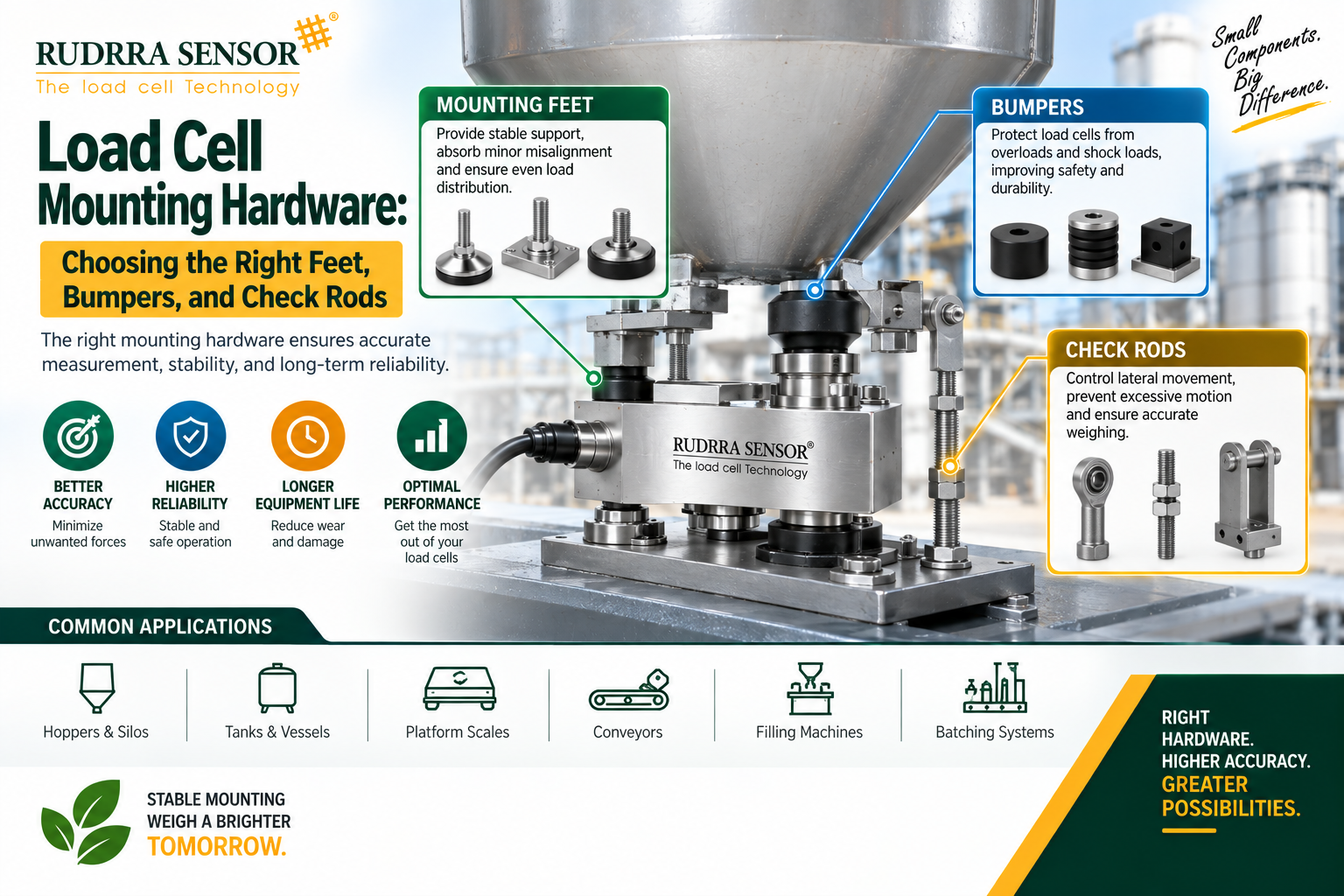
Quick answer: Load cell mounting hardware — mounting feet, bumpers (also called anti-sway or wind restraints), and check rods (also called uplift or tie-down rods) — is what transfers a structure’s weight onto the load cell along the correct axis while protecting the cell from horizontal shock, wind load, seismic movement, and uplift forces it was never designed to measure. Choosing the wrong hardware, or skipping it to save cost, is one of the most common reasons a perfectly good load cell produces an inaccurate or unstable weight reading in the field.
That sentence covers a lot of ground that most people never think about until a scale starts drifting or a tank rocks visibly in a strong wind. Let’s go through it properly.
Why Mounting Hardware Deserves Its Own Conversation
Ask most people involved in industrial weighing what determines accuracy, and they’ll talk about the load cell itself — its capacity, its accuracy class, its calibration certificate. All of that matters. But a load cell is only ever as accurate as the mechanical system that delivers force to it, and that mechanical system is the mounting hardware: the feet it sits on, the bumpers that stop a vessel from swaying into its neighbours, and the check rods that keep a lightweight tank from lifting off its supports in a gust of wind.
A load cell is fundamentally designed to measure force applied along one specific axis. Anything that introduces a side load, a twisting moment, or an uplift force onto that cell corrupts the reading, sometimes subtly enough that it looks like drift or “calibration error” rather than what it actually is — a mechanical installation problem. Engineers who have spent years commissioning tank, hopper, silo, and vehicle scales will tell you the same thing in almost identical words: most weighing system complaints that get blamed on the load cell turn out to be mounting hardware problems once someone actually climbs up and looks.
This guide covers the three hardware categories that matter most in real installations — mounting feet, bumpers, and check rods — what each one does, how to choose the right type and capacity, and the mistakes that quietly undermine weighing accuracy long after commissioning day has been forgotten.
What Mounting Hardware Actually Does
Before comparing specific products, it helps to separate the three jobs mounting hardware performs, because a single installation often needs all three working together.
Mounting feet carry the vertical load path. They sit between the structure being weighed — a tank, hopper, silo, platform, or vehicle scale deck — and the load cell itself, and they are engineered to keep the applied force acting straight down the load cell’s primary axis, even as the structure above expands, contracts, or settles slightly over time.
Bumpers (sometimes called sway stops, anti-sway restraints, or wind restraints) are mechanical stops positioned around the base of a vessel or platform that limit horizontal movement without touching the load cell’s vertical load path at all. Their entire job is to absorb horizontal force — from wind, seismic activity, agitator-induced vibration, or an operator accidentally bumping a mobile platform — before that force reaches the load cell and introduces a side-load measurement error.
Check rods (also called anti-uplift rods, tie-down rods, or hold-down rods) resist upward forces that would otherwise lift a vessel or platform off its mounting feet entirely — a real risk for lightweight tanks in high wind zones, or for any vessel where an internal process (a rapid pressure release, an agitator reversing direction, a filling nozzle catching on the vessel wall) could momentarily push the structure upward rather than down.
Put simply: feet handle the load path you want measured, bumpers stop the horizontal forces you don’t want measured, and check rods stop the vessel from leaving its load cells altogether under an upward force. Skipping any one of the three is a design compromise, not a cost saving, even though it’s frequently treated as the latter.
Load Cell Mounting Feet in Detail
Mounting feet are not a single generic part — the right choice depends on the load cell type, the expected range of thermal expansion and structural movement, and whether the installation needs to accommodate any deliberate misalignment during commissioning.
Fixed (rigid) mounting feet bolt the load cell directly between two flat plates with no built-in freedom of movement. These suit smaller, lighter installations where thermal expansion and structural deflection are minimal, and where the mounting surfaces can realistically be machined or shimmed flat and level during installation. They are the simplest and least expensive option, but they offer no forgiveness for misalignment — if the mounting surfaces are not properly parallel, a fixed foot installation will introduce a permanent side-load error that no amount of recalibration will fix.
Self-aligning mounting assemblies incorporate a rocker pin, spherical washer, or similar mechanism that allows a small amount of angular movement between the load cell and the mounting surface, automatically compensating for minor misalignment, thermal expansion, or structural settling without transferring that movement into the load cell as a measurement error. These are the standard choice for tank, hopper, and silo weighing, where some degree of structural movement over the vessel’s lifetime is not just possible but expected.
Low-profile mounting kits reduce the overall height of the load cell and mounting hardware stack, useful where headroom under a platform or vessel is limited, or where a retrofit needs to match an existing structural clearance that wasn’t originally designed with weighing hardware in mind.
High-capacity mounting assemblies for large storage silos or reactor vessels are built with substantially heavier base plates, larger self-aligning mechanisms, and correspondingly higher-rated bolting, since the absolute forces involved — and the consequences of a mounting failure — scale up dramatically with vessel size.
The material of the mounting foot matters as much as its geometry. Mild steel feet, painted or galvanized, suit indoor or dry environments where corrosion risk is low. Stainless steel feet are the standard specification for outdoor installations, washdown environments common in food and pharmaceutical processing, and any coastal or high-humidity site where corrosion would otherwise progressively degrade the mounting surface and, eventually, the accuracy of the installation.
Bumpers: The Hardware Nobody Notices Until It’s Missing
Bumpers rarely get specified with the same care as the load cell itself, largely because their job — stopping horizontal movement — isn’t something anyone sees happen under normal conditions. That’s exactly the problem. A vessel or platform sitting on load cells is not rigidly fixed to the ground the way it would be on solid feet without weighing hardware; the whole point of a load cell installation is that the structure floats slightly on the load cells so that its weight is transmitted vertically. That same freedom that makes accurate weighing possible also makes the structure vulnerable to horizontal movement from wind, seismic activity, or mechanical disturbance, unless something is specifically designed to limit it.
Bumpers are typically positioned in pairs or sets of four around the base of a tank or platform, with a small design gap — commonly just a few millimetres — between the bumper and the vessel wall or platform frame under normal, static conditions. This gap is deliberate: it allows the structure to move freely enough for the load cells to register an accurate reading without any contact friction, while limiting how far the structure can actually travel before the bumper makes contact and absorbs the excess horizontal force mechanically, rather than letting it reach the load cell as a side load.
Getting that gap right is a genuine engineering judgment call. Too tight, and the bumper makes contact during ordinary thermal expansion or minor structural flex, silently absorbing part of the load that should be reaching the load cell and producing a weighing error that looks exactly like a calibration problem. Too loose, and the structure can move far enough under a genuine wind or seismic event to introduce significant side-load error into the load cells before the bumper ever engages — or in a severe enough event, move far enough to damage the load cell or its mounting entirely.
Bumper design also has to account for the specific hazard profile of the site. A tank in a region with strong prevailing winds needs bumpers sized and positioned around its likely wind-loaded face, not just symmetrically distributed as an afterthought. An installation in a recognized seismic zone needs bumper capacity and gap dimensions calculated against the relevant local seismic design code rather than a generic industry default, since the horizontal forces involved in a seismic event can be an order of magnitude larger than routine wind loading.
Check Rods: Keeping the Vessel Where It Belongs
Check rods solve a problem that’s easy to overlook until you’ve seen it happen: a lightweight vessel, sitting freely on load cells to allow accurate weighing, has no inherent resistance to being lifted upward. Most people intuitively think of load cells as supporting weight from below and assume gravity alone keeps everything in place. In practice, several realistic scenarios can generate a genuine upward force on a vessel:
- High wind loading on a tall, lightweight tank can generate enough uplift on the windward or leeward structure, depending on tank geometry and wind direction, to partially or fully unload one or more load cells.
- Rapid internal pressure changes — a pressure relief event, a sudden vacuum condition, or an agitator malfunction — can momentarily push against the vessel structure in a way that produces upward force at specific points.
- Seismic events generate both horizontal and vertical acceleration components, and the vertical component can genuinely lift a lightweight structure momentarily during strong ground motion.
- Filling or discharge dynamics in certain process configurations, particularly pneumatic conveying systems feeding into a hopper or silo, can occasionally generate transient upward forces at the vessel’s connection points.
Check rods are installed as tension members — vertical or near-vertical rods anchored between the vessel structure and the support steelwork below — specifically to resist this upward movement while still allowing the small amount of vertical travel a load cell installation needs to function accurately. They are deliberately not rigid connections; a properly designed check rod system includes enough built-in clearance or a compliant element (a spring washer stack, an elastomeric bushing, or a similarly designed slip mechanism) that normal weighing movement is unaffected, while genuine uplift events are arrested before the vessel can separate from its mounting feet.
Sizing check rods correctly requires an actual uplift force calculation specific to the vessel’s geometry, wind exposure category, and (where relevant) seismic zone classification — not a generic “one rod per corner” rule of thumb applied without engineering justification. Under-sized check rods can fail during the exact event they were installed to protect against; over-tightened or poorly designed check rod systems can introduce a constant, unwanted preload into the load cells that shows up as measurement error even under completely calm conditions.
How Poor Mounting Hardware Corrupts Weighing Accuracy
It’s worth spelling out mechanically why mounting hardware failures masquerade so convincingly as load cell problems, because this is the single most common troubleshooting trap in industrial weighing.
A load cell’s strain gauge sensing element is calibrated to respond to force applied along a specific axis, within a specified tolerance for off-axis loading. When mounting hardware fails to keep the applied force on that axis — because a foot has corroded and seized at an angle, because a bumper is making unintended contact and diverting part of the load path, or because thermal expansion has shifted a vessel’s contact point on its mounting feet — the load cell is being asked to measure a force vector it was never calibrated against. The output doesn’t necessarily fail obviously; it often just reads slightly wrong, in a way that can look exactly like normal drift, environmental effects, or a marginal calibration issue.
This matters enormously in multi-load-cell installations — tank, hopper, and silo weighing systems commonly use three or four load cells summed together — because a mounting problem at just one corner doesn’t just add a flat offset to the total reading. It can introduce a genuinely inconsistent error that changes with fill level, temperature, or even wind conditions on a given day, since the geometry causing the problem interacts with all of those variables. Maintenance teams chasing this kind of intermittent, condition-dependent error frequently replace or recalibrate load cells that were never actually the problem, because nobody thought to inspect the mounting feet, bumper clearances, or check rod tension first.
Selecting Mounting Hardware by Application
Different weighing applications place genuinely different demands on mounting hardware, and a specification that’s perfectly adequate for one context can be dangerously under-built for another.
Tank and vessel weighing — particularly outdoor storage tanks and process vessels — represents the application where all three hardware categories typically come together: self-aligning mounting feet to accommodate thermal expansion of the vessel shell, bumpers sized against the site’s wind exposure, and check rods calculated against both wind uplift and, where applicable, seismic design requirements.
Silo weighing faces similar considerations to tank weighing but often at a larger scale, with correspondingly heavier mounting assemblies and a filling process (frequently pneumatic) that can introduce its own transient dynamic loading beyond simple static weight.
Hopper scales feeding a batching or blending process typically see more frequent load cycling than a storage tank, since material is added and discharged regularly rather than sitting at a stable level for extended periods — this argues for mounting hardware with good fatigue characteristics at the connection points, not just static capacity.
Platform and floor scales generally see less wind and seismic exposure than outdoor vessels but face a different challenge: repeated impact loading from vehicles or material handling equipment driving on and off the platform, which argues for robust bumper and check-rod-equivalent restraint at the platform edges to prevent the deck from shifting laterally under repeated impact.
Vehicle and weighbridge scales deal with dynamic loading from vehicles entering and braking on the scale deck, generating horizontal forces that a stationary tank installation never experiences, which is why weighbridge mounting hardware is typically engineered specifically for that dynamic horizontal load case rather than adapted from static vessel mounting designs.
Suspended or hanging scale configurations, less common but used in specific bulk material handling and crane-scale applications, invert the usual mounting logic entirely — here the load cell hangs in tension, and the relevant hardware consideration shifts toward swivel or self-aligning tension links rather than compression-oriented feet, though the underlying principle of keeping force on-axis remains identical.
Environmental and Regulatory Considerations
Mounting hardware selection cannot be separated from the environment the installation actually sits in, and several factors deserve specific attention during specification.
Wind exposure classification. Regional wind design codes classify sites by expected wind speed and exposure category, and this classification should directly drive bumper sizing and gap dimensions rather than being treated as a generic afterthought — a coastal or open-plain installation faces meaningfully different wind loading than a sheltered urban site.
Seismic zone classification. Similarly, local seismic design codes define expected horizontal and vertical ground acceleration values that should feed directly into both bumper and check rod sizing calculations for any installation in a recognized seismic risk zone.
Corrosion environment. Coastal sites, chemical processing environments, and food/beverage washdown areas all accelerate corrosion of mounting hardware at very different rates. Stainless steel construction, appropriate surface coatings, and periodic inspection schedules should be matched to the specific corrosion risk rather than defaulting to a generic mild steel specification because it was cheaper at the time of purchase.
Temperature range and thermal expansion. Large vessels, particularly those with significant temperature swings between empty and full or between seasons, can experience genuine dimensional change in their support structure. Self-aligning mounting feet are specifically designed to absorb this movement without transferring it into the load cell as an error, but the amount of movement the hardware can accommodate needs to be checked against the actual expected thermal range of the installation, not assumed to be adequate by default.
Hazardous area classification. Installations in explosive atmosphere zones may require mounting hardware finishes and materials — non-sparking coatings, specific bolt grades — that align with the site’s broader hazardous area compliance requirements, coordinated with whatever intrinsically safe or explosion-proof load cell specification is already in use.
Installation Best Practices
Correct hardware selection only pays off if the installation itself is done properly. Several practices separate installations that hold their calibration for years from those that need constant attention.
Verify mounting surface flatness and levelness before final bolting. Even self-aligning feet have a limited range of angular compensation; a mounting surface significantly out of level asks the self-aligning mechanism to work at the edge of its design range constantly, rather than as an occasional correction for minor movement.
Torque bolting hardware to the manufacturer’s specified values, not “tight.” Under-torqued mounting bolts can work loose under cyclic loading; over-torqued bolts on certain self-aligning assemblies can restrict the very movement the assembly was designed to allow, effectively converting a self-aligning foot into a rigid one.
Set bumper gaps with a feeler gauge or specified shim, not by eye. The design gap is a calculated dimension, not an aesthetic judgment, and installation crews should be given the actual specified clearance rather than left to estimate “a small gap” during commissioning.
Check rod pre-tension should follow the design specification exactly. A check rod installed too tight introduces a constant unwanted load into the weighing system; installed too loose, it delays engagement until the vessel has already moved further than intended before the rod takes up the uplift force.
Inspect load cell cable routing relative to all mounting hardware. Cables routed too close to a bumper’s design travel path can be pinched or damaged during an actual wind or seismic event — exactly the moment the system most needs to be functioning correctly.
Schedule periodic mounting hardware inspection, not just load cell recalibration. A calibration technician checking a load cell’s electrical output has no visibility into whether a bumper gap has closed up due to structural settling, or whether a check rod has corroded at its anchor point. A separate mechanical inspection — checking bumper clearances, foot alignment, check rod condition, and general corrosion state — should be part of any serious ongoing maintenance program for an outdoor or process vessel weighing installation.
Common Mounting Hardware Mistakes
Certain mistakes show up repeatedly across installations, industries, and geographies, which suggests they stem from predictable gaps in the specification and commissioning process rather than bad luck.
Specifying load cell capacity without specifying matching mounting hardware capacity. A mounting foot or check rod rated below the load cell’s own capacity becomes the weak point in the system, and in an overload event, it’s the mounting hardware that fails first — sometimes catastrophically, and always in a way that damages the load cell it was supposed to protect.
Treating bumpers as optional on “calm” sites. Even sites with historically low wind exposure can experience an unusual weather event, and the cost of adding bumpers during initial installation is a small fraction of the cost of retrofitting them after an incident has already caused damage or introduced a chronic measurement error.
Reusing mounting hardware from a decommissioned installation without re-verifying its rating. Hardware salvaged from a smaller or differently-configured prior installation may look physically compatible while being significantly under-rated for a new vessel’s actual load and force requirements.
Ignoring check rods on lightweight vessels because “it’s not windy here.” Uplift risk is a function of vessel geometry and internal process dynamics as much as external wind — a lightweight, tall, narrow vessel can be vulnerable to uplift forces that have nothing to do with the site’s general wind climate.
Painting over corrosion on mounting feet instead of addressing it structurally. A cosmetic fix on a corroding mounting foot leaves the underlying structural degradation in place, and the eventual failure point is rarely announced in advance.
Assuming self-aligning feet eliminate the need for careful initial alignment. Self-aligning mechanisms compensate for a limited range of angular misalignment; they are not a substitute for reasonably careful initial installation, and pushing a badly misaligned installation to the edge of the mechanism’s compensation range from day one leaves no margin for the additional movement that will occur over the vessel’s lifetime.
Load Cell Type and Mounting Hardware: How They Interact
Different load cell geometries impose different demands on the mounting hardware around them, and treating “mounting hardware” as a one-size-fits-all accessory misses this interaction entirely.
Compression-style load cells — the column and canister types typically used in large tank and silo installations — sit purely in compression, with mounting feet designed to spread the load evenly across the cell’s loading surface while preventing any lateral creep of the vessel structure relative to the cell. Self-aligning top and bottom plates are especially important here, since these cells are highly sensitive to any bending moment introduced by an uneven mounting surface.
Shear beam load cells, more commonly used in platform, floor, and smaller tank scales, tolerate a modest degree of side loading by design, which gives some additional margin if mounting hardware alignment is slightly imperfect — but this tolerance is a safety margin, not a licence to skip proper alignment procedure, since relying on a cell’s off-axis tolerance to compensate for genuinely poor installation quietly erodes the accuracy margin the cell was designed to provide for actual process variability.
S-type load cells, frequently used in hanging or suspended weighing configurations, invert the usual mounting logic since the cell operates in tension rather than compression. Mounting hardware here typically takes the form of swivel eye bolts or clevis-and-pin arrangements rather than feet, and the equivalent of a “check rod” concern becomes ensuring the suspension point cannot swing or twist in a way that introduces a side load into the cell’s tension axis.
Load pins, built into an existing structural pin at a pivot or shackle point, sidestep the mounting-foot question entirely since the cell effectively is the connection hardware. The equivalent concern for load pins is bushing wear and pin alignment at the joint itself, which plays a similar role to bumper and check rod maintenance in a conventional foot-mounted installation — both are mechanical wear points that silently degrade measurement accuracy if left uninspected.
Understanding which category a given installation’s load cells fall into is the starting point for selecting compatible mounting hardware, rather than assuming a generic “load cell foot” part number will suit any cell dropped into the specification.
The Economics of Getting Mounting Hardware Right the First Time
Mounting hardware is a small fraction of a weighing system’s total installed cost — commonly a low single-digit percentage of the overall project once civil work, load cells, junction boxes, cabling, and instrumentation are included. That small proportion is precisely why it gets shortchanged during value engineering reviews, and precisely why doing so is a poor trade.
Consider the realistic cost comparison. Specifying stainless steel self-aligning feet instead of painted mild steel might add a modest premium to the initial hardware invoice. Skipping that premium and dealing with a corroded, seized foot three years into an outdoor installation means: a site visit to diagnose what initially looks like a calibration problem, a period of inaccurate weighing data that may have already affected inventory reconciliation or billing accuracy, the cost of the replacement hardware itself (now at current pricing rather than the original quote), and the labour cost of an unplanned mechanical intervention rather than a scheduled one.
The same logic applies even more sharply to bumpers and check rods, precisely because their failure mode is binary rather than gradual. A mounting foot slowly seizing gives some warning through gradually worsening accuracy. A missing or under-sized check rod on a lightweight tank gives no warning at all until the specific wind or process event it was designed to resist actually occurs — at which point the outcome ranges from a damaged load cell to, in a severe enough case, actual structural displacement of the vessel.
Framed as total cost of ownership across the installation’s service life rather than as a line item on the original purchase order, correctly specified mounting hardware is close to always the cheaper choice, and the cases where it looks expensive are almost always cases where the true cost of getting it wrong simply hasn’t been priced in yet.
Retrofit Considerations: Upgrading Mounting Hardware on an Existing Installation
Not every mounting hardware decision happens at initial installation. A meaningful share of the work in this space involves retrofitting better hardware onto an existing vessel or platform — often triggered by a persistent accuracy complaint, a near-miss incident during a storm, or a broader plant reliability initiative.
Retrofitting mounting feet on a vessel that’s already in service requires careful sequencing, since the vessel typically cannot be fully unloaded during the changeover without disrupting production. Temporary support arrangements, staged one-corner-at-a-time replacement procedures, and a clear understanding of the vessel’s structural tolerance for brief asymmetric loading during the changeover are all part of a properly planned retrofit, rather than something to improvise on the day.
Adding bumpers or check rods to an installation that was originally specified without them is often more straightforward than replacing feet, since it typically doesn’t require disturbing the existing vertical load path at all — new restraint hardware can usually be welded or bolted to the surrounding support steelwork independently. This makes bumper and check rod retrofits a relatively accessible improvement for facilities reviewing older installations that predate more rigorous wind or seismic design awareness, or that were originally installed in a lower-risk configuration that has since changed — a taller vessel added nearby altering local wind flow patterns, for instance, or an updated seismic code reclassifying the site’s risk category.
Any retrofit project should include an updated engineering calculation for the new hardware rather than simply matching whatever was on a similar vessel elsewhere on site — vessel geometry, local micro-siting, and accumulated structural changes over the years can all shift the correct specification meaningfully from what a “similar” installation used previously.
A Comparison Reference: Mounting Hardware at a Glance
| Hardware Type | Primary Function | Typical Application | Key Selection Factor |
| Fixed mounting feet | Rigid vertical load transfer | Small platforms, indoor scales with minimal movement | Mounting surface flatness |
| Self-aligning mounting feet | Vertical load transfer with angular compensation | Tanks, hoppers, silos with thermal/structural movement | Compensation range vs expected movement |
| Low-profile mounts | Vertical load transfer in restricted height | Retrofits, confined under-platform clearance | Available headroom |
| Bumpers / sway stops | Horizontal force restraint | Outdoor tanks, silos, platforms exposed to wind or seismic activity | Wind/seismic zone, gap tolerance |
| Check rods | Uplift / vertical separation restraint | Lightweight tanks, high-wind or seismic zones, dynamic process vessels | Uplift force calculation, pre-tension |
Digital Monitoring and the Future of Mounting Hardware Inspection
Most of the guidance above assumes mounting hardware inspection happens the traditional way — a technician physically visiting the site, checking bumper gaps with a feeler gauge, examining check rods and mounting feet visually for corrosion or misalignment, on a scheduled maintenance interval. That approach works, but it has an obvious limitation: it only catches a developing problem at the next scheduled visit, which could be months away from the moment the problem actually started.
A growing number of installations, particularly larger or more critical tank and silo systems, now pair mounting hardware with simple condition-monitoring additions that close this gap without requiring a full instrumentation overhaul. Contact sensors on bumpers can log how frequently and how forcefully contact actually occurs, giving maintenance teams real data on whether the design gap is holding up as intended rather than relying on the next physical inspection to reveal a problem that’s already been developing for weeks. Strain-monitoring additions on check rods can flag a pre-tension value drifting outside its designed range long before a full visual inspection would catch the same issue.
None of this replaces the fundamental engineering discipline of specifying mounting hardware correctly in the first place — a poorly designed check rod system generating useful data about its own failure is still a poorly designed check rod system. But for facilities managing dozens of outdoor vessel installations across a large site, or a small technical team responsible for weighing accuracy across multiple locations, this kind of lightweight condition monitoring is becoming a genuinely practical way to catch mounting hardware degradation between scheduled visits rather than discovering it only after accuracy has already been compromised for some time.
The broader trend worth watching is the same one reshaping industrial instrumentation generally: the line between “mechanical hardware” and “monitored asset” is blurring, and mounting hardware that was traditionally treated as a purely passive mechanical component is increasingly being specified alongside simple sensing additions that give it a voice in the same monitoring systems already tracking the load cell’s own output.
Working With Suppliers: Questions Worth Asking Before You Buy
Procurement teams sourcing mounting hardware, particularly for a new or unfamiliar application, benefit from a short list of pointed questions that separate a supplier who understands the application from one simply selling a catalogue part number.
Ask for the actual angular compensation range of a self-aligning foot, in degrees, not a marketing description. “Self-aligning” is a mechanism description, not a specification — a supplier who can immediately provide the actual compensation range understands the product; one who can’t is likely reselling a generic part without engineering input behind it.
Ask how bumper and check rod sizing calculations were performed, and whether they can be tied to a recognized wind or seismic design code. A supplier who can walk through the calculation basis, even briefly, is a meaningfully safer choice than one who quotes a “standard” size without reference to your specific site conditions.
Ask about material certification and traceability for stainless steel hardware, particularly for food, pharmaceutical, or hazardous area applications. Mill certificates and material traceability documentation matter for regulatory and audit purposes in these sectors, and a supplier should be able to provide them as a matter of course rather than as a special request.
Ask what happens if the installation’s actual conditions turn out to differ from the original design assumptions. Vessels get modified, nearby structures change local wind patterns, and seismic code reclassifications happen. A supplier willing to discuss how their hardware specification would need to change under revised conditions is signalling genuine engineering support rather than a one-time transactional sale.
Ask for reference installations in a genuinely comparable application, not just the same industry broadly. A supplier’s experience mounting load cells on indoor batching hoppers doesn’t necessarily transfer to sizing check rods for an offshore-adjacent outdoor storage tank, even though both fall under the same general “process weighing” umbrella.
A Practical Buying and Specification Checklist
Start from the load path, not the catalogue
Define the vessel or structure’s full weight range, expected horizontal forces (wind, seismic, mechanical), and any realistic uplift scenario before selecting hardware — the same discipline that applies to load cell selection itself applies equally to the hardware around it.
Match mounting hardware capacity to load cell capacity, with margin
Hardware rated below the load cell it supports becomes the system’s weak point, defeating the purpose of specifying a properly-rated load cell in the first place.
Request the manufacturer’s compensation range for self-aligning feet, not just a generic description
“Self-aligning” describes a mechanism, not a specific angular tolerance — get the actual number and compare it against your installation’s expected movement.
Get bumper gap and check rod pre-tension values as calculated figures, not installer judgment calls
These should come from an engineering calculation tied to your specific site’s wind and seismic classification, vessel geometry, and process dynamics.
Specify material and finish based on actual site corrosion risk, not habit
A mild steel specification that was fine for a previous indoor installation is not automatically appropriate for an outdoor or washdown environment on a new project.
Confirm hazardous area compatibility where relevant
If the load cells themselves are specified for a classified hazardous area, the mounting hardware finish and material need to be reviewed against the same requirements rather than assumed to be automatically compliant.
Plan for periodic mechanical inspection from day one
Build bumper gap checks, check rod condition inspection, and mounting foot corrosion review into the same maintenance calendar as load cell calibration, rather than treating mechanical hardware as a install-and-forget component.
A Representative Scenario: Outdoor Storage Tank in a High-Wind Region
Consider a mid-sized outdoor storage tank, mounted on four load cells, installed in a region with a recognized high-wind exposure classification. The specification process for this installation would typically proceed as follows.
The tank’s full and empty weights, combined with its geometry, define the vertical load range each load cell must handle, which in turn sizes the load cell capacity itself. Self-aligning mounting feet are specified to accommodate the shell’s thermal expansion across the site’s seasonal temperature range, with a compensation angle checked against the vessel’s actual structural drawings rather than assumed adequate by default.
Bumpers are then sized using the site’s wind exposure classification, positioned at all four sides of the tank’s base rather than only on the prevailing wind-facing side, since wind direction at any given site varies across the year. The design gap between bumper and tank wall is calculated to allow normal weighing movement while limiting maximum lateral travel to a value the load cells can tolerate as off-axis loading without meaningful accuracy impact.
Check rods are specified based on an uplift force calculation that accounts for the tank’s empty-condition weight (the most vulnerable state for uplift, since there is no product mass helping hold it down) combined with the site’s wind uplift coefficient for the tank’s specific geometry. Pre-tension is set to a calculated value that avoids introducing false load into the cells under calm conditions while still engaging promptly if genuine uplift force develops.
During commissioning, mounting surface levelness is verified before final bolting, bumper gaps are set using shims to the calculated dimension rather than estimated by eye, and check rod tension is verified against the specification using a torque or tension measurement method rather than “hand tight plus a turn.” The completed installation is then commissioned with a full calibration that establishes the baseline zero and span reading, against which future periodic checks — both electrical calibration and mechanical hardware inspection — are compared.
Regional Considerations for Export and Multi-Site Projects
Manufacturers and integrators supplying mounting hardware across multiple countries or regions face an added layer of complexity that a single-site domestic installation never has to consider: design codes for wind and seismic loading are not globally uniform, and neither are common corrosion environments, hazardous area classification schemes, or even bolt thread standards.
A hardware specification developed for a temperate, low-seismic domestic market does not automatically transfer to a coastal site in a cyclone-prone region, or to a facility in a zone with active seismic design requirements substantially more stringent than the original market. Export-oriented instrumentation suppliers who work across multiple regions need either in-house familiarity with the relevant design codes in each target market, or a working relationship with local structural engineers who can confirm that a proposed bumper and check rod specification actually satisfies the destination site’s requirements rather than simply the supplier’s home-market defaults.
This is also where documentation becomes genuinely important rather than a formality. A mounting hardware package shipped internationally should arrive with clear capacity ratings, material certification, and installation torque or pre-tension values in units and formats the receiving site’s engineering team can directly verify and apply, rather than requiring back-and-forth clarification during what is often a time-pressured commissioning schedule. For any organisation building or specifying weighing systems for export, treating mounting hardware documentation with the same rigour as the load cell’s own calibration certificate is a small effort that prevents a disproportionate amount of installation delay and cross-border technical confusion.
Frequently Asked Questions (FAQs)
Q1: What is the difference between a bumper and a check rod on a load cell installation?
A bumper restrains horizontal movement — it stops a vessel or platform from swaying sideways under wind, seismic, or mechanical disturbance. A check rod restrains vertical uplift — it stops the vessel from lifting away from its mounting feet under upward forces from wind, internal process dynamics, or seismic activity. They address different force directions and are often both required on the same installation.
Q2: Do I need self-aligning mounting feet for every load cell installation?
Not necessarily. Small, indoor, rigidly-supported platforms with minimal thermal movement can often use simpler fixed feet. Outdoor tanks, hoppers, and silos, where thermal expansion and structural settling are realistic over the installation’s lifetime, generally benefit from self-aligning feet to prevent that movement from introducing a side-load measurement error.
Q3: How is the correct bumper gap determined?
Bumper gap is calculated based on the site’s wind exposure classification, the vessel’s geometry and mass, and the load cell’s tolerance for off-axis loading, rather than set as a generic industry default. The gap needs to be large enough to allow normal weighing movement without contact, but small enough to limit maximum lateral travel before the bumper engages during a genuine wind or seismic event.
Q4: Can mounting hardware problems cause a load cell to fail calibration checks?
Yes, and this is one of the most common root causes behind what initially looks like a load cell calibration or drift problem. Misaligned feet, bumpers making unintended contact, or improperly tensioned check rods can all introduce off-axis loading or false preload that shows up as an inaccurate reading, even though the load cell’s own electrical calibration is unaffected.
Q5: How often should mounting hardware be inspected?
Mounting hardware should be inspected on a scheduled basis alongside routine load cell calibration checks — commonly annually for stable indoor installations, and more frequently for outdoor vessels exposed to significant weather, corrosion risk, or seismic activity. Any inspection following an actual severe weather or seismic event should also include a specific check of bumper condition and check rod integrity.
Q6: Are check rods necessary on every outdoor tank installation?
Not universally, but they should be evaluated based on an actual uplift force calculation rather than skipped by default. Lightweight, tall, or narrow vessels in exposed wind locations, or any installation in a recognized seismic zone, are the situations where check rods are most likely to be genuinely necessary rather than optional.
Q7: What material should mounting hardware be made from for outdoor or coastal installations?
Stainless steel is the standard recommendation for outdoor, coastal, washdown, or otherwise corrosive environments, since mild steel — even painted or galvanized — corrodes at a meaningfully faster rate in these conditions, and corroding mounting hardware can seize, bind, or degrade in ways that directly affect weighing accuracy over time.
Q8: Does mounting hardware need to match a specific load cell brand?
Mounting hardware needs to match the load cell’s physical dimensions, capacity rating, and mounting geometry, which is most reliably achieved by sourcing hardware designed specifically for the load cell in use, though a competent supplier can often specify compatible hardware for a load cell from a different manufacturer provided accurate dimensional and capacity information is available.
A Glossary of Key Terms
Mounting foot — The mechanical assembly that transfers vertical load from a structure onto a load cell while maintaining correct force alignment.
Self-aligning mount — A mounting foot design incorporating a rocker pin, spherical washer, or similar mechanism that compensates for minor angular misalignment or structural movement.
Bumper (sway stop) — A mechanical stop positioned around a vessel or platform base to limit horizontal movement without contacting the load cell’s vertical load path under normal conditions.
Check rod — A tension member installed to restrain upward (uplift) movement of a vessel or structure mounted on load cells.
Off-axis loading — Force applied to a load cell at an angle to its intended measurement axis, which introduces measurement error beyond the cell’s specified tolerance.
Uplift force — An upward-acting force on a structure, generated by wind, seismic activity, or internal process dynamics, capable of lifting a lightweight vessel off its mounting feet.
Wind exposure classification — A regional design categorization describing expected wind speed and site exposure, used to size bumpers, check rods, and related structural restraints.
Seismic zone classification — A regional design categorization describing expected ground acceleration during seismic events, used to size horizontal and vertical restraint hardware.
Preload — An unwanted, constant force introduced into a load cell by improperly tensioned mounting hardware, such as an overtightened check rod, which offsets the zero reading even under static conditions.
Corrosion allowance — The degree of material thickness or protective coating specified in mounting hardware design to account for expected material loss from corrosion over the installation’s service life.
Closing Thoughts
Mounting hardware rarely gets the attention it deserves during a weighing system specification, largely because it’s genuinely less interesting than the load cell itself — nobody writes excitedly about a bumper. But every experienced instrumentation engineer has a story about a “mystery” calibration drift that turned out to be a seized foot, a bumper making silent contact, or a check rod nobody thought to inspect after a storm. The load cell is usually innocent in these stories. The hardware around it is where the actual problem was hiding.
Getting mounting hardware right is not complicated, but it does require treating it as a genuine engineering decision rather than a line item to fill in after the load cell has already been chosen. Define the load path, calculate the horizontal and uplift forces the site can realistically produce, match hardware capacity and material to those numbers, and inspect it on the same schedule as the load cell’s own calibration. Do that consistently, and the mounting hardware disappears into the background the way it should — quietly doing its job, keeping every ounce of force flowing straight into the load cell where it belongs.
For engineering and procurement teams specifying a new tank, hopper, silo, or platform scale installation, Rudrra Sensors can help match load cells and compatible mounting feet, bumpers, and check rod assemblies to the actual load path, environmental exposure, and capacity requirements of the application, rather than leaving mounting hardware as an afterthought to the load cell order. Reach out to discuss the specific mounting and restraint requirements for your next weighing system installation.