


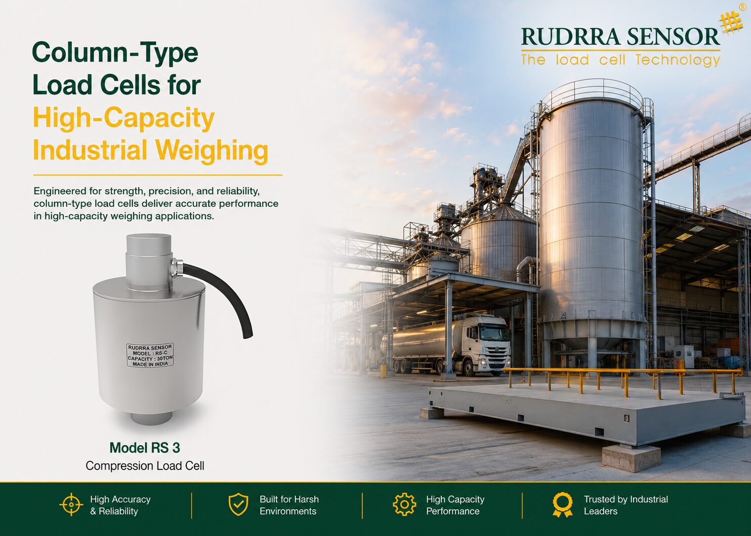
When a weighing system must handle hundreds of tonnes — when a silo holds 2,000 tonnes of cement, when a reactor vessel weighs 500 tonnes fully loaded, when a structural test frame must measure forces of tens of meganewtons — the load cell technology that makes this possible belongs to a specific class designed from the ground up for extreme capacity: the column-type load cell, also known as the canister load cell. These powerful, robust instruments occupy a unique position in the load cell family, providing the extraordinary measurement capabilities that high-capacity industrial weighing demands, in a mechanical package that can be integrated directly into the structural support systems of the largest vessels, silos, and machines in industrial manufacturing.
Column-type load cells derive their name from the cylindrical column that forms their spring element — a precisely machined, solid or hollow steel column that shortens fractionally under the compressive force applied to it. Strain gauges bonded to the outer surface of this column measure the shortening, converting it into an electrical signal proportional to the applied load. The simplicity of this mechanical principle — and the ease with which it scales to arbitrarily large capacities simply by increasing the column diameter and the strength of the steel — makes the column design the natural choice for the highest-capacity weighing applications in industry.
The importance of column-type load cells in Indian heavy industry cannot be overstated. India’s massive expansion in cement production, steel manufacturing, chemical processing, mining, fertiliser production, and infrastructure development has driven an extraordinary growth in the number and scale of high-capacity weighing systems across the country. Every cement silo, every steel ladle, every coal bunker in a power plant, every chemical reactor in a fertiliser plant, every bulk storage tank in a refinery — each of these requires load cells of capacities from tens of tonnes to thousands of tonnes, and the column-type load cell is the technology of choice for the vast majority of these applications.
This comprehensive guide covers every dimension of column-type load cell technology as it applies to high-capacity industrial weighing. We begin with the fundamental engineering principles that make column-type load cells capable of measuring such extraordinary forces accurately and reliably. We then explore the ten most important high-capacity industrial applications in depth, providing detailed technical guidance on load cell selection, installation, and the specific requirements of each application environment. A consolidated specification guide, Rudrra Sensor’s product range, and comprehensive FAQs complete the guide.
| 500+ t
Single column LC capacity for very large applications |
0.02%
Non-linearity of OIML C3 column load cells |
±0.05%
Typical zero stability per 10°C temperature change |
40+ yrs
Design service life of correctly installed column LCs |
The Case for Column-Type Load Cells
Why high-capacity weighing needs a different engineering approach
Why High-Capacity Weighing Is Fundamentally Different
A weighing engineer designing a 500 kg platform scale and a weighing engineer designing a 5,000 tonne silo weighing system face problems of entirely different character, not just different scale. The 500 kg platform scale uses shear beam load cells mounted under a steel frame, calibrated with test weights, and connected to a simple display. The accuracy requirement is achievable with standard instrumentation, the installation is straightforward, and the mechanical forces involved are within the range of common structural components.
The 5,000 tonne silo weighing system is a fundamentally different engineering challenge. The load cells must be integrated into the silo’s structural support system — they must carry the entire weight of the silo structure plus its contents, performing a structural support function while simultaneously making a precision measurement. The test weights needed for calibration weigh tens or hundreds of tonnes and are difficult to provide in the field. The structural deflections of a loaded silo create forces on the load cells that are not purely compressive — there are horizontal forces from thermal expansion, bending moments from wind loading, and dynamic forces from filling and emptying operations. And the service life requirement — 20 to 40 years of continuous structural loading — demands a mechanical design of extraordinary durability.
Column-type load cells are the engineering answer to these challenges. Their design principles — the cylindrical column spring element, the self-aligning mounting systems, the very high safe overload ratings, and the robust hermetic sealing — are specifically developed for the structural and measurement demands of high-capacity industrial weighing. Understanding why these design features exist and what they accomplish is the key to specifying and installing column-type load cells correctly.
The Structural Support Duality of Column Load Cells
Unlike a platform scale load cell that is only a measurement device, a column load cell in a silo or vessel installation is simultaneously a precision measurement instrument and a primary structural member — it carries the entire weight of the structure it is monitoring. This structural role imposes requirements that have no parallel in lower-capacity weighing: the load cell must not deflect enough to affect the structural integrity of the supported vessel; it must carry its rated load continuously for decades without creep; it must survive the overloads that occur when a silo is filled beyond its nominal capacity; and it must do all of this while maintaining its measurement accuracy to within a few hundredths of a percent. No other load cell type must simultaneously meet such demanding structural and measurement requirements.
Engineering Principles
How column load cells achieve extraordinary capacity without sacrificing accuracy
The Column Spring Element – From Concept to High-Capacity Precision
The spring element of a column-type load cell is a cylindrical column of high-strength steel, precision-machined to close tolerances in both diameter and surface finish. When a compressive force is applied to the top of the column (through a load button or loading plate) and reacted at the base (through the cell’s mounting feet or base flange), the column shortens fractionally — by an amount proportional to the applied force, governed by Hooke’s Law and the elastic modulus of the steel. For a typical alloy steel column with an elastic modulus of approximately 200 GPa, a 500 mm long column under its rated load shortens by only 0.1 to 0.3 mm — a tiny but precisely measurable deformation.
Strain gauges — four in a full Wheatstone bridge configuration — are bonded to the surface of the column at the mid-height position, where the compressive strain is most uniform and most representative of the applied load. Two gauges are oriented along the column axis (measuring compressive strain), and two are oriented circumferentially (measuring the Poisson effect — the slight diameter increase that accompanies compression). This four-gauge Wheatstone bridge arrangement has three important advantages: it cancels out the effect of temperature changes (because all four gauges change resistance equally with temperature, producing no net bridge imbalance); it doubles the output signal compared to a two-gauge arrangement; and it partially compensates for bending moments applied to the column (because bending increases strain on one side and decreases it on the other, with the bridge circuit summing these effects symmetrically).
The scaling of column load cells to very high capacities is straightforward in principle: a larger diameter column can support a larger load while maintaining the same strain level at the gauge location. For a given allowable stress in the steel (determined by material fatigue considerations), the load capacity scales with the cross-sectional area — doubling the column diameter quadruples the capacity. In practice, column load cells are manufactured in capacities from a few tonnes to several hundred tonnes per cell, with multiple cells used in parallel for the largest applications. A typical 200-tonne column load cell has a spring element diameter of 200 to 250 mm and a height of 300 to 500 mm; a 500-tonne cell may have a spring element diameter of 350 to 400 mm.
Self-Aligning Mounting – The Critical Enabling Technology
The single most important enabling technology for accurate column load cell performance in structural applications is the self-aligning mounting system. In any real installation — a silo on a concrete foundation, a vessel on a steel support frame, a weighbridge deck on a pit structure — the loading surfaces are never perfectly parallel, the structural members flex under load, and thermal expansion introduces angular changes between the base and the top of the load cell. If the load cell is rigidly mounted, these imperfections impose bending moments on the spring element, which corrupt the measurement and create stresses that reduce the cell’s structural fatigue life.
The self-aligning mounting system — the most common design being the cup-and-ball or rocker pin assembly — solves this problem elegantly. The load cell sits in a cup-shaped recess machined to receive a spherical ball or rocker pin at its base. When the structure above the load cell deflects or the foundation below settles slightly, the ball rotates freely in the cup, accommodating the angular change without transmitting any bending moment to the load cell body. The result is that the load cell sees only pure compressive force — the force it was designed to measure — regardless of minor misalignment in the installation.
For silo and vessel applications, this self-aligning capability is essential because the vessel and its foundation are not rigid: the vessel deflects under load, the foundation settles over time, and thermal cycling causes the vessel support legs to expand and contract by millimetres. Without self-aligning mounts, these movements would introduce significant errors and would impose bending fatigue that would eventually crack the load cell spring element. With self-aligning mounts, these movements are accommodated without affecting either measurement accuracy or structural integrity.
Hollow Column Design for Specific Applications
In addition to the solid cylindrical column, column-type load cells are also manufactured with hollow cores — a cylindrical annular spring element rather than a solid column. The hollow column design has two advantages: first, a hollow column of the same outer diameter and same rated capacity as a solid column is lighter (important for reducing the tare weight of the load cell itself in some applications); second, the hollow core can be used to route cables, pass through a process pipe, or accommodate an anchor bolt — allowing the load cell to be integrated into structural assemblies that would otherwise require a solid column to be installed alongside rather than in place of a structural element.
Key Performance Parameters and Their Significance
| Parameter | Typical Column Load Cell Specification | Engineering Significance |
| Rated Capacity | 10 t to 500 t (single cell); multi-cell systems to several thousand tonnes | The fundamental selection parameter; select with minimum 20% margin above maximum load |
| Non-Linearity | ≤0.02% FS (OIML C3); ≤0.05% FS (OIML C2) | Determines accuracy of inventory calculation from weight measurement; critical for custody transfer |
| Hysteresis | ≤0.02% FS | Important for vessel filling/emptying cycles; limits achievable accuracy over a fill cycle |
| Creep (30 min) | ≤0.02% FS | Critical for continuous inventory monitoring; drift appears as apparent weight change |
| Temperature Effect on Zero | ≤0.020% FS per 10°C | Causes apparent weight change with temperature; important for outdoor and process-heated vessels |
| Temperature Effect on Span | ≤0.015% FS per 10°C | Changes the calibration with temperature; must be within acceptable limits for the application |
| Safe Overload | ≥150% of rated capacity | Defines the load the cell survives without permanent damage; critical for silo overfilling scenarios |
| Ultimate Overload | ≥300% of rated capacity | The load at which mechanical fracture occurs; provides structural safety reserve |
| IP Rating | IP67/IP68 standard; IP69K for wash-down | Defines environmental sealing; IP67+ essential for outdoor and process vessel installations |
| Material | Alloy steel (general industrial); 316L SS (corrosive/food/pharma) | Material selection determines chemical compatibility and service life in aggressive environments |
| Fatigue Life | 10M+ cycles at rated load | Relevant for dynamic applications; structural installations see fewer but larger load cycles |
| OIML Class | C2, C3, or C4 | Accuracy class for legal-for-trade, inventory, or custody transfer applications |
Column vs Canister vs Other High-Capacity Designs
Understanding the terminology and the distinctions that matter for specification
Navigating the Terminology — Column, Canister, and Related Designs
The terminology for high-capacity compression load cells can be confusing, with different manufacturers using different terms for similar designs. For the purposes of this guide and for practical specification purposes, the following distinctions are useful:
Column Type / Solid Column
The classic cylindrical solid column design. The spring element is a solid steel cylinder. Load is applied at the top through a loading button or spherical seat and reacted at the base flange. Available in capacities from approximately 10 to 500 tonnes per cell. The solid column provides maximum stiffness and minimum deflection per unit load — important for structural applications where the load cell must not deflect significantly under load to maintain the geometry of the supported structure.
Canister Type
A cylindrical housing that encloses the entire sensing mechanism, including the spring element, strain gauges, cable, and sealing. The canister design integrates all these elements in a factory-sealed assembly that provides excellent environmental protection and simplified installation. In practice, the terms ‘column type’ and ‘canister type’ are often used interchangeably in the industry, as most modern high-capacity compression load cells use a canister housing around a column or similar spring element.
Low-Profile / Button Type at High Capacity
For applications where height is severely constrained — such as under existing vessel legs or in pits with limited clearance — low-profile compression load cells (also called pancake or disc type) are used at capacities up to 5,000 kN. These are technically distinct from column cells — their spring element is a disc rather than a column — but they serve overlapping applications and are sometimes included in discussions of high-capacity load cells.
Hollow Core Column
As described above — an annular (hollow) spring element that allows through-routing of cables, pipes, or anchor bolts. Used where structural integration requires that an existing structural element (such as a leg support or anchor bolt) passes through the load cell.
| Design Variant | Typical Capacity Range | Profile Height | Best Application | Material Options |
| Solid Column | 10 t – 500 t | 150–500 mm | Silo support, vessel weighing, large structure monitoring | Alloy steel, 316L SS |
| Hollow Column | 50 t – 500 t | 150–450 mm | Through-bolt installations, pipe-routing applications | Alloy steel, 316L SS |
| Canister (with column element) | 5 t – 1,000 t | 100–600 mm | General high-capacity weighing, outdoor vessels | Alloy steel, 316L SS, CS |
| Low-Profile Disc | 1 t – 500 t | 25–100 mm | Press monitoring, height-constrained vessel support | Alloy steel, 316L SS |
| Multi-Stage Column | 100 t – 5,000 t | 200–1,000 mm | Very high capacity structural support, ship loaders | Special alloy steel |
High-Capacity Application Guide — Column Load Cells in Heavy Industry
Bulk Silo and Hopper Weighing — Cement, Grain, Minerals
The most widespread high-capacity column load cell application — continuous inventory monitoring of bulk solids storage
Overview
Bulk silos are the defining infrastructure of the cement, grain, mining, fertiliser, and chemical industries. A large cement plant may have a dozen or more silos, each holding 500 to 3,000 tonnes of cement, raw meal, coal, or fly ash. A major grain elevator may have hundreds of bins and tanks, each holding thousands of tonnes of wheat, rice, maize, or soybeans. A potash mine’s surface plant may have silos holding 50,000 tonnes of refined potash awaiting export. In every case, knowing accurately and continuously how much material is in each storage vessel is essential for production planning, quality management, logistics, and commercial settlement with suppliers and customers.
Column-type load cells are the standard solution for silo and hopper weighing at capacities above approximately 50 tonnes. Three or four column load cells are positioned under the silo legs or structural supports, each with a self-aligning cup-and-ball or rocker pin mounting assembly. The combined output of all cells — summed in a load cell junction box — gives the total weight of the silo and its contents. By subtracting the known tare weight (the weight of the empty silo structure), the net weight of the contents is calculated and displayed continuously in the plant’s DCS, SCADA, or ERP system.
The accuracy achievable with column load cell silo weighing systems depends on the quality of the load cells, the installation engineering, and the compensation for environmental variables. With OIML C3 class column load cells, correctly installed with self-aligning mounts, and with adequate compensation for the effects of temperature on the structural steel and the load cells themselves, silo weighing systems regularly achieve inventory accuracy of ±0.1% to ±0.2% of the silo’s full capacity — sufficient for all industrial inventory management purposes and for most commercial settlement applications.
Technical Considerations
- The silo foundation and support structure must be rigid enough that the load cell measurements are not compromised by differential foundation settlement — consult a structural engineer before installing load cells on any silo without a recent structural assessment
- Wind loading on exposed outdoor silos imposes lateral forces on the silo structure and on the load cells — select column load cells with adequate side-force tolerance, and install horizontal check rods (anti-sway restraints) to prevent the silo from moving laterally in high winds
- Thermal expansion of the silo structure (which can be 5-20 mm for a 10 metre steel silo in full Indian summer-to-winter temperature range) imposes horizontal forces on the load cells unless the mounting system accommodates this expansion — rocker pin or self-aligning cup-and-ball mounts are essential
- Dynamic loading during silo filling (from the impact of rapidly inflowing material) can significantly exceed the static weight — select column load cells with overload ratings that accommodate filling dynamics, and install mechanical overload stops
- Dust and vibration from pneumatic conveying systems filling the silo require IP67 minimum sealing for load cells and IP66 for junction boxes; signal filtering in the indicator is essential to provide stable readings during filling
- For cement silos, the extremely fine and penetrating nature of cement dust requires meticulous attention to cable entry sealing and junction box integrity — cement infiltration into electrical connections causes insulation failure and measurement errors
Key Benefits
- Continuous real-time inventory data eliminates manual level measurement, which is hazardous in confined space environments and inaccurate for bulk solids with variable bulk density
- Automated low-level alarms prevent costly production stoppages from material shortages — particularly valuable for continuous process industries where a raw material shortage stops the entire production line
- Overfill protection through high-level alarms prevents structural overloading of the silo — a critical safety function given the catastrophic consequences of silo structural failure
- Accurate inventory data supports just-in-time procurement, reducing storage costs by allowing lower safety stock levels without increasing the risk of stockouts
- Weight-based consumption monitoring (comparing inventory at batch start and end) provides accurate specific consumption data for process efficiency monitoring
Recommended Column Load Cell Specification
Type: Column or canister type; self-aligning cup-and-ball or rocker pin mounting hardware
Number of Cells: 3 cells for three-legged silos; 4 cells for four-legged or rectangular structures
Capacity: Match to 1.3× maximum gross weight (silo tare + maximum fill)
Material: Alloy steel for general industrial; 316L SS for outdoor exposed and food-contact applications
IP Rating: IP67 minimum; IP68 for outdoor installations in areas subject to flooding
Output: 4-20 mA to DCS/SCADA; Modbus RTU for digital integration; net weight calculation in indicator or DCS
Large Chemical Storage Tank Weighing
Column load cells in acid, caustic, and process chemical storage — where weight measurement also serves safety
Overview
Chemical storage tanks — holding sulphuric acid, sodium hydroxide, liquid ammonia, phosphoric acid, liquid chlorine, or any of dozens of other process chemicals — are among the most safety-critical vessels in any chemical manufacturing or processing plant. Knowing the accurate inventory of these chemicals at all times is important for production management (knowing when to order replenishment), for environmental compliance (tracking chemical usage and potential emission sources), and for safety management (monitoring for unexpected inventory changes that might indicate a leak or a process upset that is consuming more chemical than planned).
Column-type load cells under large chemical storage tanks provide the continuous inventory monitoring that serves all these functions. For a sulphuric acid tank at a fertiliser plant, for example, the load cell system continuously displays the mass of acid in the tank — updated every few seconds. If the mass decreases at a rate inconsistent with the known consumption rate of the process, the load cell system’s alarm triggers an investigation before a small leak becomes a large release. This load cell-based leak detection capability is particularly valuable for chemicals whose concentration or density varies with conditions, making level-based measurements unreliable.
The material compatibility requirements for chemical storage tank load cells are the most demanding of any industrial application. The load cells must survive not only the mechanical loads of supporting a full tank, but also the chemical environment of the tank surroundings — which typically includes vapour, spills, and cleaning operations with the stored chemical. For sulphuric acid storage, for example, even trace acid contamination of alloy steel load cells causes rapid corrosion that destroys the spring element within months. Only austenitic stainless steel (AISI 316L or higher alloy grades such as Hastelloy C-276) provides adequate corrosion resistance for long-term service in acid environments.
Technical Considerations
- Chemical compatibility must be established for every material in the load cell — spring element, housing, seals, cable jacket, and gland — before specifying for a chemical storage application; consult the load cell manufacturer’s chemical compatibility data
- 316L SS is appropriate for dilute acids, caustic solutions, and most industrial chemicals; Hastelloy C-276 or Inconel 625 may be required for concentrated acids, oxidising environments, and chloride-containing solutions
- ATEX certification is required for tanks holding flammable chemicals — liquid ammonia, solvents, and flammable process chemicals all have hazardous area zones around their storage tanks
- Anti-lift restraints (uplift anchors) are required for tanks that may become buoyant under flooding conditions or that are subject to vacuum suction forces during emptying — these restraints prevent the tank from lifting off the load cells while still allowing accurate weight measurement
- Flexible pipe connections are essential for all process piping, steam tracing, and utility connections to the weigh vessel — rigid connections create parallel load paths that cause systematic measurement errors
- For outdoor chemical tanks, thermal expansion compensation is critical — a 10 metre diameter tank filled with liquid can expand by several centimetres in full sun, imposing significant forces on the load cells if the mounting does not accommodate this
Key Benefits
- Direct mass measurement is immune to density variations with temperature and concentration — more reliable than level-based inventory for chemicals with variable properties
- Leak detection through unexpected mass loss rate monitoring provides an early warning system that complements conventional leak detection methods
- Environmental permit compliance monitoring — accurate chemical usage and inventory data supports regulatory reporting requirements
- Elimination of hazardous manual tank dipping or entry for level measurement — load cell-based inventory monitoring removes the need for personnel to approach hazardous chemical tanks for routine measurement
- Safety system integration — low-mass alarm can trigger automatic isolation of chemical feed valves before the tank runs empty and allows air ingress
Recommended Column Load Cell Specification
Type: Column or canister LC; 316L SS minimum; Hastelloy for concentrated acid/oxidiser service
Capacity: 1.3× maximum gross weight (tank tare + maximum fill + dynamic allowance for filling surge)
IP Rating: IP68 minimum; outdoor tanks may be flooded; chemical environments require all seals verified
ATEX: Required for flammable chemical tanks; confirm zone classification from site hazardous area drawing
Flexible Connections: All process piping must use flexible hose at tank connection — rigid pipes create parallel load paths
Anti-Lift: Install uplift restraints on tanks that may be subject to buoyancy or vacuum forces
Weighbridge and Truck Weighing at Very High Capacity
Column and double-ended beam load cells for axle loads exceeding 30 tonnes — heavy transport and mining applications
Overview
Standard truck weighbridges for road transport handle gross vehicle weights up to 49 tonnes (the legal maximum for most Indian state roads) using load cells rated at 30 to 50 tonnes per cell. But in mining, port, and heavy industrial environments, the vehicles are considerably larger: mining dump trucks (rigid haul trucks) used in open-cast coal and iron ore mines can gross 300 to 400 tonnes; port reach stackers and heavy-lift vehicles used in steel plant logistics can weigh 200 tonnes unladen; and specialised multi-axle transport vehicles used for moving large industrial equipment can reach axle loads of 50 tonnes or more. These applications demand high-capacity column-type load cells that go far beyond the specification of a standard road weighbridge.
For permanent weighbridge installations at mine truck dispatch points — where every truck departure is weighed to calculate payload and verify that gross weight limits are not exceeded — column or double-ended shear beam load cells of 50 to 100 tonnes capacity per cell are standard. A typical 6-metre-wide mining truck weighbridge with 8 load cells, each rated at 80 tonnes, provides a system capacity of 640 tonnes — adequate for the largest rigid haul trucks in Indian mining operations. The deck is a heavy structural steel plate supported on the load cells, with deep pit foundations to accommodate the load cell height and the drainage requirements of the pit.
For dynamic weighing at high vehicle speeds — where trucks are weighed at speed without stopping — high-frequency column or piezoelectric load cells embedded in the road surface measure axle loads in the brief time each axle is on the sensor. These weigh-in-motion (WIM) applications require load cells with very high natural frequencies (hundreds of Hz) to capture the dynamic load accurately in the milliseconds of contact time. High-capacity column cells with appropriately designed mounting for road-embedded service are available for this demanding application.
Technical Considerations
- Mining truck weighbridges are installed in outdoor locations with heavy vehicle traffic, stone dust, fuel and hydraulic oil spillage, and severe vibration from truck operations — IP68 is the minimum practical standard for load cells in mining weighbridge pits
- The deck structure of a mining truck weighbridge must be designed to transmit only vertical loads to the load cells — deck beams must be free to span between load cells without imposing bending moments, requiring careful structural design of the deck cross-section
- Dynamic impact loading from truck wheels crossing the bridge at speed creates overloads of 1.2 to 1.5× the static axle load — load cells must have safe overload ratings of at least 150%, and mechanical overload stops must limit travel to prevent ultimate overload in the event of an emergency
- For high-frequency WIM applications, the load cell’s natural frequency must exceed 10× the highest frequency component of the dynamic axle load signature — typically requiring natural frequencies above 500 Hz for WIM at highway speeds
- OIML C3 certification is mandatory for all legal-for-trade weighing applications — including payload monitoring for mining trucks where the weight data is used for commercial settlement
Key Benefits
- Accurate payload measurement at every truck dispatch optimises truck loading — maximising payload per trip while preventing overloading that damages tyres, suspension, and haul roads
- Legal-for-trade accuracy at the mine gate supports commercial settlement with customers and prevents disputes over delivered quantities
- Overload detection prevents damage to haul roads and bridges from overloaded trucks — reducing road maintenance costs that are a major operational expense in open-cast mining
- Automated ticketing from weighbridge systems eliminates manual recording errors and provides complete electronic records of every truck movement for logistics and production management
Recommended Column Load Cell Specification
Type: Double-ended shear beam (standard weighbridge) or column type (very high capacity pit installations)
Capacity: 50–100 t per cell for mining trucks; system capacity 4× to 8× maximum vehicle gross weight
IP Rating: IP68 minimum for pit-mounted load cells; IP69K if high-pressure water cleaning used in pit
Material: 316L SS for outdoor pit installations subject to water and chemical exposure
OIML: C3 mandatory for legal-for-trade payload measurement; certification verified annually
Dynamic Overload: Safe overload ≥150% for impact at bridge entry; mechanical stops essential
Steel Industry — Ladle Weighing and Furnace Charging
Column load cells handling the most extreme combination of high capacity, dynamic loading, and high temperature in any industrial application
Overview
The steel industry presents some of the most demanding conditions for column-type load cells in any industrial application. A steel ladle — the large refractory-lined vessel that holds molten steel between the steelmaking furnace and the continuous caster — typically holds 100 to 300 tonnes of steel at temperatures above 1,600°C. Accurately measuring the weight of steel in the ladle is important for several reasons: steel is sold by weight, making ladle weighing a commercial measurement; the carbon and alloy content of steel is adjusted based on the known weight of the melt; and the amount of steel poured into each caster strand is controlled by the ladle weight signal.
Column-type load cells used for ladle weighing face extraordinary demands. The load cell itself must support the weight of the ladle and its molten steel contents — up to 400 tonnes in a large steelwork — while sitting on the ladle turret (the rotating structure that moves ladles between the tap stand, trim station, and casting position). The thermal environment is extreme: radiant heat from the hot ladle and the steelmaking furnace raises ambient temperatures to 80-120°C in the vicinity of the load cells, requiring extended-temperature-range load cells and effective thermal shielding. And the dynamic loading from the crane placing the ladle on the turret creates impact loads of 1.2 to 1.5× the static ladle weight.
Column load cells for furnace charging — measuring the weight of scrap steel, ferroalloys, and other materials added to an electric arc furnace or basic oxygen furnace — operate in similarly extreme environments. The charging materials are typically loaded into a charge basket by overhead crane; the basket weight is monitored by column load cells in the crane’s hoist structure or on a dedicated charge weighing station. Accurate charge weight control is important for steel composition — the amount of each ferroalloy determines the final chemistry of the steel product.
Technical Considerations
- Ladle weighing load cells must be rated for continuous operation at ambient temperatures of 80-120°C with short-term excursions to higher temperatures during ladle placement — specify extended temperature range cells with compensation to at least +120°C
- Thermal shielding (refractory fibre insulating panels, water-cooled shields, or reflective steel baffles) between the hot ladle and the load cell mounting is essential to maintain the load cell within its rated temperature range
- Impact loading from ladle placement requires safe overload ratings of at least 200% and fatigue-rated load cells capable of surviving millions of ladle placement cycles over the equipment’s service life
- The high magnetic field environment near electric arc furnaces can induce currents in load cell cables, causing interference — shielded cables and signal isolators are essential
- Steel industry environments involve high levels of electromagnetic interference from arc furnaces, frequency drives, and high-current power cables — specify load cell signal conditioners with galvanic isolation and robust EMC filtering
- Ladle weighing for commercial steel measurement must meet national weights and measures standards — OIML C3 class load cells and verified calibration are mandatory
Key Benefits
- Accurate ladle weight measurement supports correct alloy addition calculations, directly determining final steel composition and product quality
- Commercial steel weight measurement from ladle weighing provides the mass data for customer invoicing and internal production accounting
- Continuous ladle weight monitoring during teeming (pouring into the caster) enables control of the teeming rate and detection of ladle approaching empty before a cold pour contamination incident
- Charge weight control in electric arc furnaces reduces ferroalloy consumption by eliminating over-addition — important given the high cost of specialty ferroalloys
Recommended Column Load Cell Specification
Type: Column or canister LC; high-capacity (100–500 t per cell); extended temperature range
Temperature: Compensated range to +120°C minimum; thermal shielding to maintain cell below +80°C preferred
Impact Loading: Safe overload ≥200% of rated capacity; fatigue-rated for millions of ladle placement cycles
EMC: Shielded cable; signal conditioner with galvanic isolation and EMC filtering for arc furnace areas
OIML: C3 for commercial weighing; verified calibration per national weights & measures regulations
Thermal Shielding: Refractory insulation panel or water-cooled shield between ladle and load cell is essential
Coal Bunker and Power Plant Fuel Inventory
Column load cells in power plant coal bunkers and oil tank farms — continuous fuel inventory for uninterrupted generation
Overview
A coal-fired thermal power plant is critically dependent on maintaining adequate coal inventory in its coal bunkers — the storage vessels that feed coal directly to the pulverisers and combustion system. A typical 500 MW generating unit has 6 to 8 coal bunkers, each holding 500 to 800 tonnes of coal, providing 8 to 16 hours of generation at full load. If the bunker inventory falls below minimum, the pulverisers must be throttled back, reducing generation output. If a bunker runs empty, the unit must trip (shut down) until coal supply is restored — an event with significant commercial and grid stability implications.
Column-type load cells under coal bunkers provide the continuous, reliable inventory monitoring that prevents these events. The load cell signals are integrated into the plant’s distributed control system (DCS), which continuously calculates the coal inventory in each bunker, the current consumption rate (from the feeder speeds and coal density), and the projected time to minimum inventory. This data drives automatic alerts to the plant operator and to the coal logistics system when replenishment is required.
Power plant environments are demanding for column load cells. The coal dust environment requires IP65 minimum sealing. The vibration from bunker feeders, pulverisers, and the overall plant structure requires signal filtering. The thermal environment in the bunker area — which may be warm from the adjacent boiler structure — requires temperature compensation. And the commercial importance of the coal inventory data (used for fuel cost accounting, environmental emissions reporting based on coal consumption, and operational efficiency monitoring) requires OIML C3 class load cells with verified calibration.
Technical Considerations
- Coal dust is a significant fire and explosion hazard — ATEX Zone 21 certification is required for load cells in enclosed coal bunker rooms where coal dust can accumulate to explosive concentrations
- Bunker internal coal flow can create bridging (arching) that shifts the weight distribution across the load cells — the DCS must sum all cell outputs rather than using individual cell readings; single-cell failures must be detectable and alarmed
- Vibration from bunker feeders (typically belt feeders or chain conveyors running continuously) must be filtered — specify digital averaging in the indicator; take design readings between feeder cycles if possible
- Coal has variable bulk density (typically 700-900 kg/m³ depending on type and moisture content) — load cell weight measurement is not affected by bulk density variation, making it superior to level-based measurement for coal bunkers
- The long service life requirements of power plant equipment (25-40 years) demand column load cells with comprehensive documentation, proven reliability records, and manufacturer support for spare parts and calibration over this period
Key Benefits
- Real-time coal inventory prevents unplanned generation curtailment from fuel shortage — one of the highest-impact performance metrics for a thermal power plant
- Consumption rate monitoring from continuous weight data enables early detection of coal feeder malfunction — before a bunker runs empty unexpectedly
- Fuel cost accounting using actual weighed coal consumption (rather than calculated consumption from feeder speed) improves the accuracy of unit heat rate calculation and environmental emissions reporting
- Automated coal logistics management — triggering coal reclaim from stockpiles when bunker levels fall below threshold — improves the efficiency of coal handling operations
Recommended Column Load Cell Specification
Type: Column or canister LC under bunker support legs; 3-4 cells per bunker
ATEX: Zone 21 (dust) certification required for enclosed coal bunker rooms
IP Rating: IP65 for coal dust; IP67 for outdoor bunker areas or areas subject to water washing
Capacity: 1.3× maximum gross weight (bunker tare + maximum coal fill); typically 100–500 t per cell
Vibration: Signal averaging essential; consider self-cleaning cup-and-ball mounts for dusty environments
Service Life: Specify 25-year rated service life; request fatigue life documentation from manufacturer
Large Hydraulic Press and Forging Press Force Monitoring
Column load cells in the tie rods and platens of large industrial presses — force measurement at meganewton scale
Overview
Large hydraulic presses — used for forging, forming, compacting, extruding, and pressing a wide range of materials from steel billets to refractory ceramics — are among the most powerful machines in manufacturing. A large open-die forging press may develop forces of 10,000 to 80,000 kN (10 to 80 MN) — forces that require load cells of extraordinary capacity and structural robustness to measure reliably. Column-type load cells, either integrated into the press tie rods as instrumented members or mounted in the press platen structure, provide the force measurement capability needed for these extreme applications.
For tie-rod-mounted column load cells, the standard approach is to replace the conventional tie rod nut or tie rod section with an instrumented column that carries the full tie rod load. As the press closes and develops clamp force, the column load cells in the tie rods register the tension (which is directly related to the clamp force acting between the platens). For very large presses with tie rod diameters of 200 to 500 mm, the column load cells must have rated capacities of several MN per tie rod — well within the capability of large-diameter solid column designs.
In addition to static force measurement during the press cycle, column load cells in large press structures provide valuable condition monitoring data. Over the service life of a large press, the press frame can develop structural asymmetries from wear, misalignment, or accumulated fatigue damage. By monitoring the force in each of the four tie rods individually, engineers can detect developing asymmetry — for example, if one tie rod is consistently carrying 30% more force than the others, this indicates a platen alignment problem that will cause differential wear on the tooling and, if uncorrected, may lead to tie rod failure.
Technical Considerations
- Very large press tie rod load cells must be precision-machined to the same tolerances as the tie rod itself — dimensional errors in the load cell body affect the press alignment and the load cell measurement accuracy equally
- Press platen temperatures (from heated dies or from the adiabatic heating of the worked material) impose thermal loads on adjacent load cells — verify temperature compensation range covers the actual platen temperature at the load cell mounting location
- The dynamic force profile of a hydraulic press stroke — rapid initial force build-up as the die contacts the work piece, peak force during forming, pressure relief at stroke end — requires adequate load cell frequency response to capture this profile accurately
- Very high press forces create significant structural deflection of the press frame and platens — the load cell mounting must accommodate this deflection without imposing bending moments; self-aligning mounting is essential even in press applications where alignment appears good at zero load
- Scale effects: for presses developing forces above 10 MN, the tie rod load cells may be the primary measurement reference for force calibration of the press — their calibration traceability must be impeccable, ideally traceable to a national force standard
Key Benefits
- Direct force measurement at the tie rods provides the actual force applied to the workpiece — more accurate than hydraulic pressure inference, which is subject to seal efficiency and friction losses
- Tie rod force balance monitoring detects press alignment problems before they cause tooling damage or press frame overloading
- Press force data logging provides the quality record required for aerospace, power generation, and other critical applications where forging force is a mandatory process parameter
- Long-term press force monitoring enables accurate calculation of press frame fatigue life, supporting evidence-based decisions about press refurbishment or replacement
Recommended Column Load Cell Specification
Type: Column LC integrated into tie rod structure; or high-capacity pan cake under platen for direct force path monitoring
Capacity: Match to maximum tie rod load at maximum press force with 1.3× safety factor; range 1 MN to 50 MN for large presses
Temperature: Extended range compensation to +180°C if near heated tooling; thermal shielding as required
Calibration: National force standard traceability for presses used in aerospace and critical structural forgings
Frequency Response: ≥50 Hz for press cycle force profile monitoring; higher for impact forming operations
Tie Rod Integration: Custom dimensional design to match press tie rod geometry — work with manufacturer on special designs
Ship Loader and Port Bulk Material Handling
Very high-capacity column load cells in ship loaders, grab cranes, and conveyor belt scale systems at ports and bulk terminals
Overview
Bulk material ports — handling coal, iron ore, grain, fertilisers, cement, and other commodities in multi-million tonne annual volumes — represent some of the most demanding load cell applications in terms of both capacity and environmental exposure. A large ship loader conveyor delivering coal to a Panamax bulk carrier at 5,000 tonnes per hour develops belt forces and structural loads that require column load cells at the very high end of the capacity range. The port environment — salt air, tropical rainfall, and the mechanical environment of continuous heavy-duty bulk material handling — places exceptional demands on load cell environmental protection.
Column-type load cells in ship loaders and bulk terminal equipment serve two primary functions. First, in the structural support of the ship loader tower, boom, and conveyor structure: the self-weight of a large ship loader may exceed 1,000 tonnes, and the structural supports that carry this weight must be instrumented to monitor the actual structural loads and detect any structural anomaly that could indicate developing fatigue damage or foundation movement. Column load cells integrated into the ship loader’s structural support system provide continuous monitoring of these loads, with alarms if the load distribution deviates significantly from the design values.
Second, in the conveyor belt scale systems that measure the tonnage of material loaded into each vessel: column or shear beam load cells in the conveyor weigh idler frames provide continuous mass flow measurement, integrating to give the total tonnage loaded into each hold. This measurement is the primary basis for the Bill of Lading quantity — the commercial document that defines how much material the customer is being charged for — making accuracy and reliability critical commercial requirements.
Technical Considerations
- Marine port environments impose severe corrosion demands — salt air, humidity, and the occasional direct saltwater splash from ship operations; 316L SS load cells are the minimum; duplex stainless steel or super duplex for the most exposed locations
- Ship loader structural load cells must handle very high dynamic loads from the combined effects of ship movement, conveyor loading, and wind — dynamic overload factors of 1.3 to 1.5 are typical, with associated requirements for fatigue-rated load cells
- For conveyor belt scales at ports, the OIML accuracy class must be appropriate for custody transfer measurement — typically C3, and subject to verification by the port authority’s weights and measures inspector
- Dust sealing for column load cells under conveyor structures must be IP67 minimum — fine mineral or coal dust in port bulk handling can infiltrate IP65 sealing in the long term
- Lightning protection is essential for structural monitoring load cells on ship loaders and similar tall exposed structures — transient suppression diodes and proper earthing of all metal components are necessary
- Cable routing must protect against mechanical damage from material spillage (coal lumps, rock fragments, grain) falling from conveyors and grab cranes — armoured cable and metal conduit are essential
Key Benefits
- Structural load monitoring of ship loader boom and tower structure provides continuous safety assurance — detecting developing structural problems before they reach critical levels
- Conveyor belt scale accuracy meets Bill of Lading requirements, providing the commercial measurement data that defines the customer’s charge and eliminates disputes over loaded quantities
- Load monitoring data supports the ship loader structural inspection programme — identifying areas of the structure subjected to higher-than-design loads for priority inspection
- Integration with the port’s cargo management system enables automatic creation of cargo documentation from the weighed tonnage data, reducing manual administration and transcription errors
Recommended Column Load Cell Specification
Type: Column or double-ended shear beam for structural monitoring; shear beam for conveyor belt scales
Capacity: Structural monitoring: 100–1,000 t per cell; conveyor belt scale: 50–500 kg weigh idler capacity
Material: 316L SS minimum; super duplex for direct marine exposure
IP Rating: IP68 for all marine port installations; IP69K for any area subject to pressure cleaning
OIML: C3 for custody transfer conveyor belt scales; statutory verification by port authority
Lightning: Transient suppression at every cable entry; equipotential bonding of all metal structures
Mining and Aggregate — Crusher and Conveyor Load Monitoring
High-capacity column load cells in crushing circuits, screen decks, and primary conveyor structures
Overview
Mining and quarrying operations — whether producing coal, iron ore, limestone, granite, sand, or aggregates — involve enormous material flows through large-capacity crushing, screening, and conveying systems. Column-type load cells in these systems provide structural load monitoring (verifying that equipment is operating within its design load limits), process flow measurement (measuring the tonnage of material through each stage of the process), and inventory monitoring (weighing stockpiles and surge bins). The mining environment — dust, water, vibration, and the mechanical impact of large rock fragments — is among the most challenging for any instrumentation.
In primary crushing circuits, the feeders that deliver run-of-mine ore to the primary crusher are typically apron feeders or reciprocating plate feeders, with the feeder pan supported on column-type load cells. The load cell output provides an indication of the mass of ore on the feeder, and the rate of change of this mass (combined with the feeder speed) gives the mass throughput rate. This measurement is used to control the crusher feed rate — maintaining the crusher at its optimal feed rate for maximum productivity while avoiding overloading. In large mining operations, this feed rate control from load cell data can improve crusher throughput by 5-10% compared to speed-only control.
Surge bins and coarse ore bins in mining and aggregate plants — the intermediate storage vessels between crushing stages — are another important application for column-type load cells. These bins can hold 100 to 2,000 tonnes of crushed material and must be monitored to prevent overfilling (which can damage the bin structure) and running empty (which can cause downstream process interruptions). Column load cells under the bin support structure provide the continuous inventory data needed to manage these bins effectively.
Technical Considerations
- Mining and quarrying environments are extremely dusty, wet, and subject to severe vibration — IP67 load cells with vibration-resistant cable connections are the minimum; IP68 for any underground mining application or surface installation subject to flooding
- Rock and ore impact loading on feeder-mounted load cells is severe — the free-fall of large rock fragments onto the feeder apron creates dynamic impact forces many times the static material weight; column load cells must have safe overload ratings of at least 300% for primary crusher feeder applications
- Conveyor belt scale load cells in mining operations must be fatigue-rated for the very high number of loading cycles — a conveyor operating at 1,000 cycles per hour accumulates 8.7 million cycles per year, requiring fatigue-rated shear beam or low-profile compression cells
- For underground mining applications, ATEX Zone 1 certification is required in areas where methane gas may be present — this includes most coal mine applications
- The magnetic content of iron ore, magnetite, and other ferromagnetic minerals can affect load cell readings if the magnetic field is inhomogeneous across the load cell spring element — verify magnetic compatibility with the ore being weighed
Key Benefits
- Feed rate control using load cell data improves crusher throughput and reduces specific energy consumption per tonne of crushed product
- Surge bin inventory monitoring prevents both overfilling (bin structure overload) and running empty (process interruption) — both of which have significant operational and safety consequences
- Structural monitoring of large crushing and conveying equipment detects developing problems (bearing failures, structural cracks, foundation settlement) before they cause catastrophic failure
- Mass balance monitoring across the crushing and conveying circuit enables accurate calculation of process efficiency and identification of material losses
Recommended Column Load Cell Specification
Type: Column or canister LC for surge bin support; low-profile or shear beam for feeder monitoring
Capacity: Surge bins: 1.3× maximum bin weight; feeders: 3× static material weight for impact allowance
IP Rating: IP67 minimum surface; IP68 for underground and flood-risk locations
ATEX: Zone 1 IIC for coal mines; Zone 21/22 for surface areas with coal or mineral dust
Impact Overload: Safe overload ≥300% for primary crusher feeders; mechanical stops essential
Magnetic: Verify non-magnetic or low-magnetic load cell construction for ferromagnetic ore applications
Large Reactor and Pressure Vessel Weighing
Column load cells in fertiliser, petrochemical, and specialty chemical reactors — weighing vessels that are themselves critical process equipment
Overview
The largest process reactors in fertiliser production, petrochemical processing, specialty chemical synthesis, and oil refining can weigh hundreds of tonnes when fully loaded — filled with catalyst, reaction mixture, and the heat exchange and structural components of the vessel itself. Accurately weighing these reactors during operation provides inventory data on catalyst loading (how much catalyst remains in the reactor, which depletes over time), reactant addition (how much raw material has been added to the batch), and product yield (how much product has been formed or removed).
Column-type load cells in large reactor installations face the combined challenges of high capacity (the reactor may weigh 100 to 500 tonnes when full), high temperature (many reactors operate at elevated temperatures that create thermal loads on adjacent structures), and chemical aggressiveness (the reactor contents and the process atmosphere around the reactor may be corrosive to all but the most resistant materials). Despite these challenges, load cell-based reactor weighing is widely used in fertiliser and petrochemical plants because it provides information — actual mass of contents — that cannot be obtained by any other measurement method without penetrating the reactor pressure boundary.
For continuous reactors in refinery and petrochemical service — fluid catalytic crackers (FCCs), hydrotreaters, reformers — structural monitoring using column load cells detects abnormal loads that could indicate fouling, catalyst channelling, or structural damage inside the reactor. A gradual increase in the reactor’s apparent weight over time indicates catalyst or coke accumulation; a sudden shift in load distribution between the reactor’s support legs indicates a possible internal structural failure. These measurements provide insights into reactor condition that are otherwise unobtainable without shutting down and opening the vessel.
Technical Considerations
- Process vessel temperature can heat the reactor shell, skirt, and support structure to temperatures well above ambient — load cells must be rated for the actual temperature at the mounting location, which may be 60-120°C above ambient depending on insulation and design
- High-pressure reactors (operating at 50-300 bar) have flanges, piping connections, and vessel nozzles that impose significant forces on the vessel structure — flexible connections and careful installation engineering are essential to prevent these forces from appearing as measurement errors
- Catalyst dust and process chemical vapours create aggressive environments for load cells around reactors — 316L SS with IP67 is standard; Hastelloy or special alloy for the most corrosive petrochemical environments
- ATEX certification is required for all load cells in petrochemical reactor areas — Zone 1 for most refinery applications; confirm zone classification from the plant’s area classification drawing
- For safety-critical applications (where the reactor weight measurement is used for a safety system decision), the load cell system must meet the applicable SIL (Safety Integrity Level) requirements, which may require redundant load cells and voting logic in the control system
Key Benefits
- Catalyst inventory monitoring from reactor weight data enables optimised catalyst replacement scheduling — replacing catalyst on the basis of actual remaining catalyst mass rather than a fixed time interval can significantly extend catalyst utilisation
- Reactant addition control from reactor weight data provides mass-based addition control that is immune to density variations — superior to flowmeter-based control for variable-density process streams
- Reactor condition monitoring through load distribution data provides ongoing structural surveillance without requiring reactor shutdown or entry
- For batch reactors, precise reactant addition by weight provides the traceable dosing records required by pharmaceutical cGMP and specialty chemical ISO quality standards
Recommended Column Load Cell Specification
Type: Column or canister LC on reactor skirt or support legs; 3-4 cells; capacity 1.3× maximum gross weight
Temperature: Extended range to +120°C; thermal insulation of support structure to reduce heat conduction to load cells
Material: 316L SS standard; Hastelloy C-276 for chlorinated or oxidising process atmospheres
ATEX: Zone 1 for refinery and petrochemical reactor areas — mandatory; confirm zone classification
SIL: Safety-critical applications: SIL assessment; redundant load cells; 2oo3 or 1oo2 voting logic
Pressure Connections: All process connections to reactor must use flexible hose or bellows — rigid pipes create parallel load paths
Structural Load Monitoring in Infrastructure and Construction
Column load cells in foundations, bridges, test frames, and structural health monitoring systems
Overview
The monitoring of forces in structural members — the columns, foundations, pile caps, cables, and joints of bridges, buildings, dams, offshore platforms, and industrial structures — is a growing application for high-capacity column-type load cells. As infrastructure assets age and as structural integrity management becomes increasingly important for safety and economic reasons, the ability to measure actual loads in critical structural members provides a level of structural surveillance that visual inspection and analytical calculation alone cannot achieve.
In new construction, column-type load cells are embedded in pile caps, caisson heads, or structural joints during construction to measure the actual loads imposed on these elements during and after construction. This ‘instrumented construction’ approach allows designers to verify that the structure is actually experiencing the loads predicted by analysis, identifies areas where the design assumptions were not met (perhaps because of differential settlement, unexpected construction sequence effects, or material property variations), and provides baseline data for long-term structural health monitoring.
In existing infrastructure, column-type load cells can be installed under the supports of bridges (between the bridge superstructure and the bearing pad), in the legs of offshore platforms (at the sea floor interface where corrosion and fatigue are most critical), under the columns of industrial buildings (to detect differential foundation settlement that could cause structural damage), and in the cable anchor blocks of suspension and cable-stayed bridges (where cable tension is a primary safety-critical parameter). This installed structural monitoring capability transforms an otherwise invisible structural system into a continuously measured, data-rich engineering asset.
Technical Considerations
- Structural monitoring load cells are installed for very long service lives — 25 to 50 years for most infrastructure applications — requiring exceptional stability of the load cell’s zero and sensitivity over this period; specify low creep (≤0.02% per 30 min) and low long-term drift (≤0.1% per year)
- Outdoor infrastructure load cells face the full range of environmental exposure — UV, rain, flooding, temperature extremes from -10°C to +60°C in Indian conditions; IP68 and UV-stable materials are the minimum standard
- Data acquisition for structural monitoring is typically continuous at low frequencies (1-10 Hz) rather than at high speed — 4-20 mA output is standard, with optional digital communication for integration with structural health monitoring platforms
- In earthquake-prone areas, load cells must survive the dynamic forces of design-basis earthquake events without being permanently damaged — the overload specification must account for earthquake forces, which can be several times the static service load
- Structural monitoring load cells must be installed in accessible locations where they can be visually inspected and replaced if necessary during the structure’s service life — inaccessible installations (completely embedded in concrete, for example) must be designed for a single installation lifetime without replacement
- For bridge and offshore platform applications, the load cell data must integrate with the structure’s structural health monitoring (SHM) system — verify digital communication compatibility and data format compatibility before specification
Key Benefits
- Actual measured structural loads replace analytical assumptions with verified data — providing engineers with confidence that safety margins are genuinely adequate, not merely calculated
- Early detection of abnormal load distribution (from differential settlement, creep, or structural damage) allows intervention before the structural condition reaches the point of requiring emergency repair or closure
- Long-term load history data from structural monitoring enables fatigue life prediction based on actual measured loads — a significant improvement over design-code fatigue calculations based on assumed load spectra
- For new infrastructure, instrumented construction data provides valuable feedback on the accuracy of design assumptions — improving the design of future similar structures and potentially reducing unnecessary conservatism
Recommended Column Load Cell Specification
Type: Column or canister LC; long-term stability specification essential; self-aligning mounts critical
Capacity: Match to 1.5× maximum expected structural load including dynamic and earthquake loads
Long-Term Stability: Zero drift ≤0.1% per year; creep ≤0.02% per 30 min; request long-term stability data from manufacturer
IP Rating: IP68 minimum; UV-stable cable and housing; rated for full temperature range
Output: 4-20 mA continuous; optional Modbus/RS-485 for SHM system integration
Service Life: Request 25-year minimum rated service life documentation; spare parts availability assurance
Installation Engineering for Column-Type Load Cells
The engineering decisions that determine whether a high-capacity system achieves specification performance
Foundation and Support Structure Requirements
The foundation and support structure for a column-type load cell installation must be designed with the same rigour applied to any structural engineering project — because that is precisely what it is. The load cell mounting points must be:
- Sufficiently rigid that the deflection of the mounting surface under the maximum load is less than the self-aligning capability of the mounting hardware — typically less than 2 to 5 mm of differential deflection between adjacent load cell mounting points
- Sufficiently strong that the maximum load (including overload factors) can be supported without yielding or permanent deformation of the mounting surface
- Level to within the angular range accommodated by the self-aligning mount — typically ±3° for cup-and-ball mounts; larger angles require special designs
- Provided with anti-corrosion protection appropriate for the service life of the installation — epoxy paint or galvanising for mild environments; stainless steel baseplates for corrosive environments
- Designed to accommodate the thermal expansion of the supported vessel — either through adequate flexibility in the mounting arrangement, or by incorporating thermal isolation (PTFE pads, for example) that reduces the force transmitted to the load cells by thermal expansion
Self-Aligning Mount Selection and Installation
The choice and correct installation of self-aligning mounting hardware is one of the most critical decisions in a high-capacity column load cell installation. The primary options are:
Cup-and-Ball Assembly
A hardened steel ball (typically 60-150 mm diameter depending on load cell capacity) rests in a matching spherical recess in the upper cup and lower cup. The ball can rotate freely within a defined angular range (typically ±3° to ±5°), accommodating minor angular misalignment between the top and bottom of the load cell. Cup-and-ball assemblies are the most widely used self-aligning mount for vessel and silo applications. They require periodic inspection and lubrication to ensure free movement over the decades of the installation’s service life.
Rocker Pin Assembly
A cylindrical or profiled pin rolls on a matching curved surface, accommodating angular movement in one direction while constraining movement in the perpendicular direction. Rocker pin assemblies are used where the direction of misalignment is known and predictable — for example, under a tank where thermal expansion occurs primarily in one direction. They provide excellent load transfer efficiency and are preferred for very high-capacity applications where the ball-and-cup design would require very large ball diameters.
Load Button with Hardened Seat
For lower-capacity applications and where the structural misalignment is small, a simple load button (a hemispherical protrusion on the top of the load cell) resting on a hardened, flat seat provides a degree of self-alignment through the Hertzian contact mechanics of the sphere-on-flat interface. This is the simplest and most compact self-aligning arrangement, but it has a smaller angular accommodation range than cup-and-ball assemblies.
Commissioning and Initial Calibration
The commissioning of a high-capacity column load cell installation requires particular care because the calibration method — applying certified test weights to the full capacity of the system — is impractical for most high-capacity applications. A 2,000-tonne silo cannot be calibrated by loading it with 2,000 tonnes of certified test weights. Instead, the following approaches are used:
- Substitution weighing: a portion of the system’s range is verified with certified test weights, and the full-range performance is inferred from the verified linearity and span of the load cells
- Dead weight comparison: the system is loaded with a material of known density (water, for example) and the weight calculated from the measured volume is compared with the load cell reading
- Comparison with another measurement: a flow meter or other measurement device whose accuracy has been verified independently is used to cross-check the load cell measurement over a period of operation
- Factory calibration traceability: the individual load cells are factory-calibrated with certified test equipment traceable to national force standards (NABL in India) and the system’s performance is predicted from the individual cell calibration data combined with the system design
For legal-for-trade applications (where the load cell measurement is used for commercial billing or custody transfer), the verification method must meet the requirements of the applicable national standard — in India, the Legal Metrology Act and the Rules thereunder. For critical industrial monitoring applications, any of the above methods that demonstrates the system’s performance within the required accuracy is acceptable, provided the method and results are fully documented.
Column Load Cell Specification Guide
Consolidated selection parameters for high-capacity industrial applications
| Parameter | High-Capacity Requirement | Selection Guidance |
| Type | Solid column, hollow column, or canister — based on installation geometry and structural integration requirements | Match to mechanical constraints; canister for general use; hollow column for through-bolt or pipe-routing applications |
| Rated Capacity (per cell) | 10 t to 500 t; selected based on number of cells and maximum load with 20-30% margin | Never select equal to maximum expected load; 1.3× is minimum; 1.5× preferred for dynamic applications |
| Number of Cells | 3 for three-point support (preferred for inherently statically determinate loading); 4 for rectangular structures | Three-point support distributes load equally without structural stiffness-dependent sharing; preferred for most vessel applications |
| Safe Overload Rating | 150% of rated capacity as absolute minimum; 200-300% for impact and dynamic applications | Silo overfilling, crane impact loading, and seismic events all produce overloads — choose safe overload conservatively |
| Non-Linearity | ≤0.02% FS for OIML C3 (inventory, custody transfer); ≤0.05% for process monitoring | Determines the accuracy of mass-derived measurements; C3 is the standard for commercial and regulatory applications |
| Temperature Range | -10°C to +70°C standard; -20°C to +120°C extended; confirm actual ambient at installation | Temperature effects on zero and span cause apparent weight changes with weather and process conditions — cover actual range |
| IP Rating | IP67 minimum for any industrial outdoor or process area; IP68 for flood-risk and pit installations | High-capacity installations are long-term (20+ years); IP rating must be maintained throughout service life — choose conservatively |
| Material | Alloy steel (general heavy industrial); 316L SS (chemical, food, outdoor exposed); Hastelloy (corrosive chemicals) | Material determines corrosion resistance and service life; steel saves cost but corrodes; stainless costs more but lasts decades |
| Self-Aligning Mounts | Cup-and-ball or rocker pin mounting hardware essential for all vessel and structural applications | Without self-aligning mounts, column load cells in structural applications suffer from bending moments and give inaccurate readings |
| Anti-Lift Restraints | Required for tanks that may be subject to buoyancy, vacuum, wind uplift, or seismic overturning forces | Anti-lift restraints prevent the vessel from lifting off the load cells while still allowing weight measurement |
| ATEX | Specify Zone 1 or Zone 2 (gas/vapour) or Zone 21/22 (dust) as required by hazardous area classification | Consult the site area classification drawing before specifying any electrical equipment — non-negotiable safety requirement |
| Output | 4-20 mA current loop as standard for SCADA/DCS integration; Modbus RTU or digital fieldbus for additional data | 4-20 mA provides reliable signal over long cable distances; digital bus enables richer data exchange with modern control systems |
| Calibration | NABL-traceable factory calibration certificate; OIML certificate for legal-for-trade; site verification at commissioning | For commercial and regulatory applications, calibration chain must trace to NABL-accredited force standards |
| Service Life | 25 years minimum for fixed structural installations; 10-15 years for dynamic press and machinery applications | Specify design service life explicitly in the URS; request manufacturer confirmation and supporting fatigue life data |
Rudrra Sensor’s Column-Type Load Cell Solutions
India’s trusted partner for high-capacity weighing in heavy industry
About Rudrra Sensor
Rudrra Sensor has been manufacturing and supplying precision load cells and weighing system components to Indian and global industrial customers since 2002. Our high-capacity column-type and canister load cell range is specifically engineered for the structural, environmental, and accuracy demands of heavy industry — cement, steel, mining, chemicals, fertilisers, power generation, and infrastructure. We supply complete high-capacity weighing solutions: load cells, mounting hardware, junction boxes, signal conditioners, and indicators, backed by application engineering expertise and comprehensive documentation.
Our High-Capacity Column Load Cell Range
- Solid Column Load Cells — alloy steel and 316L SS; IP67/IP68; capacities 10 t to 200 t per cell; for silo, vessel, and structural monitoring applications
- High-Capacity Canister Load Cells — alloy steel and 316L SS; IP67/IP68; capacities 50 t to 500 t per cell; for very large vessel support and structural applications
- Hollow Column Load Cells — alloy steel and 316L SS; capacities 50 t to 500 t; for through-bolt and pipe-routing installations
- ATEX-Certified Column Load Cells — Zone 1/Zone 2 gas and vapour certified; Zone 21/22 dust certified; for coal bunkers, chemical plants, and petroleum refineries
- Extended Temperature Column Load Cells — compensated to +120°C; for steel ladle weighing, reactor-adjacent installations, and heated process vessel applications
- Marine Grade Column Load Cells — 316L SS or super duplex; IP68; for port and ship loader structural monitoring in aggressive marine environments
- Self-Aligning Mounting Hardware — 316L SS cup-and-ball assemblies, rocker pins, and anti-lift restraint systems for complete high-capacity installation solutions
- Load Cell Junction Boxes — IP67/IP68; stainless steel enclosures; with summing resistors and trimming capability for multi-cell installations
- High-Capacity Load Cell Signal Conditioners — 4-20 mA output; for long-distance SCADA/DCS signal transmission from remote installations
- Load Indicators with Modbus/Ethernet — for display, data logging, alarm management, and digital integration with plant control systems
Application Engineering for High-Capacity Installations
High-capacity column load cell installations are engineering projects — not just instrumentation supply — and our application engineering team is experienced in supporting the full lifecycle of these projects:
- Load cell capacity and number selection: calculating the load per cell from the vessel geometry, material density, tare weight, and dynamic factors
- Mounting hardware selection: recommending the appropriate self-aligning mount type, size, and material for the specific structural geometry and environmental conditions
- Foundation and structural review: assessing whether the proposed mounting structure meets the flatness, stiffness, and load-bearing requirements for the installation
- Anti-lift restraint design: calculating the uplift forces for each application and specifying appropriate restraints
- Hazardous area guidance: confirming ATEX requirements and available certified products for each classified installation
- Commissioning support: on-site technical assistance for commissioning of complex multi-cell installations, including verification weighing and calibration documentation
- Long-term maintenance support: calibration programmes, spare parts supply, and technical support throughout the installation’s service life
Frequently Asked Questions (FAQ)
Q1: How many column load cells do I need for a silo or vessel weighing installation?
The standard is three cells for a three-legged vessel (one under each leg) and four cells for a four-legged or skirt-supported vessel. Three cells are preferred from a structural mechanics standpoint because a three-point support is inherently statically determinate — all three cells share the load equally, regardless of minor structural stiffness variations. A four-point support is statically indeterminate, which means the load sharing between cells depends on the relative stiffness of the vessel and mounting structure; if one support is slightly stiffer than the others, it carries more load, potentially overloading its load cell while the others read low. For this reason, three-cell installations are preferred whenever the vessel geometry permits. Where four-cell installations are unavoidable (square or rectangular tank bases), careful structural design and cell matching are required.
Q2: What is the difference between safe overload and ultimate overload in a column load cell?
The safe overload rating is the maximum force that can be applied to the load cell without causing a permanent change in its zero or sensitivity — typically 150% of the rated capacity. The load cell will recover fully to its original calibration after the safe overload is removed. The ultimate overload rating is the maximum force the load cell can withstand without mechanical fracture of the spring element — typically 300% of rated capacity. Between the safe overload and ultimate overload limits, the load cell may suffer permanent calibration shift (it may still function but with incorrect readings) but will not fracture. Above the ultimate overload, the spring element fractures, which can release the supported structure suddenly — a potentially catastrophic event for a loaded silo or vessel. The large safety margin between the normal operating load and the ultimate overload (typically 300% × rated capacity, which is 300%/130% = 2.3× the maximum expected load with the normal 1.3 safety margin) provides important protection against unexpected overload events.
Q3: How do I calibrate a column load cell installation when I cannot provide test weights equal to the full capacity?
For most high-capacity silo and vessel installations, full-capacity calibration with certified test weights is impractical. The standard approach for non-custody-transfer applications is to verify the system at the lower end of the range (typically 10-30% of full capacity) using certified test weights, confirm the linearity is within the load cell’s specification, and extrapolate the full-range calibration from the factory calibration data. For custody-transfer and legal-for-trade applications, substitution weighing (using a material of known density such as water to fill the vessel to a calculated weight) provides the full-range verification required by national weights and measures regulations. In all cases, the factory calibration certificate (with traceability to NABL in India) is the primary documentation for the system’s measurement accuracy.
Q4: Why do column load cell readings change with temperature, and what can I do about it?
Column load cell readings change with temperature due to two independent effects. First, temperature changes affect the load cell’s own zero output and sensitivity — these are specified as the temperature effect on zero and temperature effect on span parameters, and are compensated within the load cell by the Wheatstone bridge configuration and additional compensating elements. Second, temperature changes cause thermal expansion of the vessel structure, which can impose horizontal forces on the load cells if the mounting does not accommodate the expansion — and these horizontal forces cause apparent weight changes. The solution to the second effect is correct mounting hardware: cup-and-ball or rocker pin assemblies accommodate the thermal expansion without transmitting horizontal forces to the load cells. For the best accuracy in applications with significant temperature variation, both effects must be addressed through correct load cell specification (adequate temperature compensation range) and correct installation (self-aligning mounts with adequate horizontal movement accommodation).
Q5: What is the effect of wind on a column load cell silo installation, and how is it managed?
Wind loading on a tall silo creates a bending moment at the base of the silo — one side of the base is pushed down (increasing the load on the load cells on that side) and the other side is pulled up (decreasing the load on the load cells on the other side). For a three-cell installation, the sum of all three cell outputs equals the total vessel weight regardless of the distribution — the bending moment due to wind is self-cancelling in the sum. This is one of the key advantages of summing all cells in a multi-cell installation: wind loading does not affect the total weight reading, only the distribution between cells. However, extreme wind loading can potentially lift one leg of the silo off its load cell (if the wind moment exceeds the gravitational preload on that cell) — anti-lift restraints must be designed to prevent this while still allowing free downward movement of the cell. For very tall silos in high-wind locations, a structural engineer should assess the wind uplift forces and specify the anti-lift restraint design accordingly.
Q6: Can column-type load cells be installed in existing vessels and structures without major modifications?
In many cases, yes. For vessels with identifiable structural support points (discrete legs, a skirt with identifiable load paths), column load cells can be installed by shimming them into the existing support gap between the vessel and its foundation, or by inserting them into the support column structure. The key requirements are: sufficient vertical clearance (height) in the support structure to accommodate the load cell height (typically 150-500 mm for column cells); accessible mounting surfaces for the load cell base and top; the ability to temporarily relieve the load on each support point to install the load cell (using hydraulic jacks to slightly lift the vessel); and adequate structural integrity of the existing support structure to function reliably with load cells in place. For existing vessels where the support structure does not have accessible load paths, custom-designed load cell mounting assemblies can often be engineered to integrate into the existing structure without requiring complete removal of the vessel.
Q7: What documentation should I receive with a high-capacity column load cell for an industrial installation?
For a high-capacity column load cell in a heavy industrial application, you should receive: a factory calibration certificate with the individual cell’s zero output, sensitivity, non-linearity, and hysteresis data, referencing the calibration standards used (which should be traceable to NABL or equivalent); an OIML conformity certificate if the cell is supplied to an OIML accuracy class; an EN 10204 3.1 material certificate confirming the spring element and housing material composition; an IP rating test certificate confirming the actual tested ingress protection; an ATEX certificate if the cell is supplied for a classified zone; a dimensional drawing showing all critical dimensions including mounting interface geometry; and an installation and maintenance manual. For very high-capacity applications (100 tonnes and above), also request a factory test report showing the load cell’s performance under actual load conditions at the factory, rather than relying solely on the calibration certificate values.
Conclusion
Column-type load cells occupy a unique and indispensable place in industrial weighing technology. As the only load cell class capable of simultaneously serving as a structural support member and a precision measurement instrument at capacities of hundreds or thousands of tonnes, they enable the high-capacity inventory monitoring, process control, and structural surveillance that heavy industry depends on. From the cement silo that monitors 2,000 tonnes of raw material inventory in real time, to the steel ladle that tracks 300 tonnes of liquid steel through the furnace and caster, to the ship loader structure that ensures the integrity of the equipment handling millions of tonnes per year — column-type load cells are the measurement foundation that makes these operations precise, safe, and efficient.
The engineering demands on column-type load cells are commensurate with their structural role. Decades of service life, extreme environmental exposure, the highest capacity requirements in the load cell family, self-aligning mounting systems that accommodate structural movement, ATEX certification for hazardous atmospheres, and measurement accuracy sufficient for commercial and regulatory applications — all of these requirements must be met simultaneously by a single piece of precision instrumentation. Getting the specification, installation, and maintenance of column-type load cells right is therefore an engineering responsibility of the highest order, with consequences — positive when done well, negative when done poorly — that are felt at the scale of the industrial processes they serve.
Rudrra Sensor has been engineering and supplying column-type and high-capacity load cells for India’s heavy industries since 2002. Our product range — solid and hollow column cells, canister cells, ATEX-certified variants, extended temperature designs, marine grade constructions — combined with our application engineering expertise and the complete mounting hardware and signal conditioning systems needed for every high-capacity installation, makes us a comprehensive partner for every column load cell application. Our engineering team is available to help with capacity selection, mounting design, ATEX assessment, commissioning support, and long-term maintenance — providing the application depth that high-capacity industrial weighing requires.