


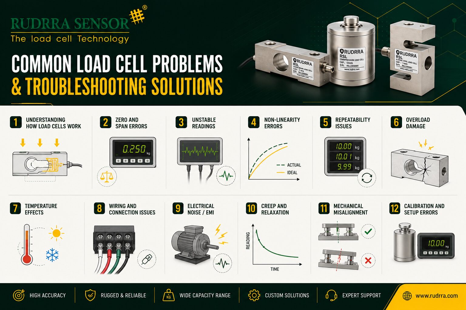
A Comprehensive Guide for Engineers, Technicians, and Maintenance Professionals
Introduction
Load cells are the silent workhorses of the modern industrial world. From the bathroom scale in your home to the multi-ton platform scales in steel mills, from pharmaceutical dosing systems to aerospace structural testing rigs — load cells are everywhere, quietly converting mechanical force into electrical signals with remarkable precision. Yet, despite their relative simplicity in design, load cells are sensitive instruments that can fail, drift, or behave erratically under a wide range of conditions.
When a load cell misbehaves, the consequences can cascade quickly. In manufacturing, inaccurate weight measurements lead to product quality failures, costly rework, and regulatory non-compliance. In process industries, a faulty load cell can trigger false alarms, halt production lines, or — in worse cases — allow unsafe conditions to go undetected. In trade and commerce, a malfunctioning weighing system can result in financial losses, customer disputes, and legal liability.
The challenge is that load cell problems are rarely simple or obvious. A load cell that reads 2% high might be suffering from a wiring issue, an environmental factor, mechanical misalignment, or electronic drift — and distinguishing between these causes requires systematic thinking, the right tools, and a solid understanding of how load cells work.
This comprehensive guide covers the most common load cell problems encountered in real-world applications, explains the underlying causes behind each failure mode, and provides practical, step-by-step troubleshooting solutions.
Understanding How Load Cells Work
Before diving into specific problems and solutions, it is worth establishing a firm understanding of load cell operating principles. This foundation makes troubleshooting far more intuitive, because most problems can be traced back to a disruption in one of the fundamental links in the measurement chain.
The Strain Gauge Principle
Most industrial load cells are strain gauge-based devices. A strain gauge is a thin, serpentine metallic foil bonded to a flexible backing, which is in turn adhesively bonded to a metal spring element (typically machined from high-alloy steel or aluminum). When a force is applied to the load cell, the spring element deforms elastically — it bends, compresses, or stretches by a precisely controlled amount. The strain gauges bonded to the spring element deform along with it, causing their electrical resistance to change proportionally to the applied force.
A single strain gauge produces a very small resistance change — typically on the order of milliohms for full-scale load. To amplify this signal and simultaneously compensate for temperature effects, four strain gauges are connected in a Wheatstone bridge configuration: two gauges in tension and two in compression. The result is an output signal typically in the range of 1 to 3 millivolts per volt of excitation (mV/V) at full-rated load.
The Signal Chain
Understanding the full signal chain helps locate where a problem is occurring:
- Mechanical Interface — The physical connection between the load cell and the structure. Problems here include misalignment, side-loading, off-center loading, binding, and shock loads.
- Spring Element — The structural heart of the load cell. Problems include overload damage, fatigue cracking, corrosion, and physical damage.
- Strain Gauges and Bonding — The sensitive measurement elements. Problems include gauge debonding, moisture ingress under the gauge, cracking, and temperature effects.
- Wheatstone Bridge Circuit — The electrical network. Problems include bridge imbalance, opens, shorts, and leakage resistance.
- Wiring and Connectors — The communication pathway. Problems include broken conductors, poor connections, moisture ingress, and electromagnetic interference (EMI).
- Indicator or Transmitter — The signal processing unit. Problems include incorrect settings, power supply issues, and electronic faults.
- Software and System Integration — The data layer. Problems include scaling errors, filtering issues, and communication faults.
Zero and Span Errors
The most frequently reported load cell complaints are variations on two themes: the reading is wrong at zero load, or the reading is wrong at a known load. Understanding the difference between zero errors and span errors is the critical first step in any troubleshooting process.
Zero Errors: When the Empty Reading Is Wrong
A zero error means the load cell or weighing system displays a non-zero value when it should display zero, or vice versa. Zero errors come in two varieties:
Static Zero Offset: Occurs when the zero reading is consistently wrong by a fixed amount. Usually correctable by re-zeroing or taring the instrument, but if the offset is large or changes over time, there is an underlying problem.
Zero Drift: A more insidious problem where the zero reading changes over time without any change in actual load. A system that reads zero correctly in the morning may read 3 kg by afternoon.
Common Causes of Zero Errors
- Temperature effects — All load cells have a temperature coefficient of zero (TC Zero). A load cell with TC Zero of 0.02%FS/°C in an environment with a 20°C temperature swing will experience a zero shift of 0.4% of full scale.
- Mechanical binding and friction — Prevents the load cell from returning to its true zero state after load is applied or removed. Check for debris, rust, or ice in moving parts.
- Moisture and contamination — Water ingress into the load cell body lowers the insulation resistance between the bridge circuit and the case ground, creating leakage that alters bridge balance.
- Shock overloads — A sudden impact can permanently shift the zero if the spring element is stressed beyond its elastic limit.
- Electrical interference — EMI from nearby motors, VFDs, or welding equipment can induce noise signals causing the displayed zero to fluctuate.
Troubleshooting Zero Errors — Step by Step
- Verify the zero with no load applied and all mechanical influences removed. Disconnect any piping, cables, or supports that might be applying a hidden force.
- Check the ambient temperature and compare with the load cell’s temperature coefficient specification. If drift correlates with temperature, consider a temperature-compensated amplifier.
- Measure the insulation resistance between the signal wires and the cable shield using a megohmmeter. Below 1000 MΩ indicates moisture ingress; below 50 MΩ is serious.
- Inspect all mechanical components for binding, debris, or ice.
- Measure the supply voltage at the load cell connector. A fluctuating supply voltage can cause apparent zero drift.
- If zero drift is large, sudden, and permanent, suspect a mechanical overload. Inspect for visible deformation.
Span Errors: When the Loaded Reading Is Wrong
A span error means the system reads correctly at zero but incorrectly at some known applied load. For instance, a scale reads zero with an empty container, but reads 98 kg when a certified 100 kg test weight is applied.
Common Causes of Span Errors
- Incorrect calibration — If the system was never calibrated with reference weights traceable to national standards, or calibration was done under different conditions, the span will be off.
- Mechanical efficiency loss — Friction, binding, or structural flexure prevents the full load from transferring to the load cell. A common example is a weighbridge with corroded pivot points.
- Load cell damage — Partial overload can permanently alter the sensitivity of the spring element, changing its output per unit of applied force.
- Wiring resistance errors — In multi-load-cell systems, unequal cable resistance causes load cells to contribute unequally to the summed output.
- Amplifier gain drift — Can cause span errors if signal conditioning electronics drift over time, more common in older analog amplifiers.
Troubleshooting Span Errors
- Apply certified test weights at the center of the load receiver. Calculate the percentage error.
- Apply the same test weight at different positions. If the reading varies with position, the problem is likely mechanical or in wiring resistance differences.
- Measure the output voltage of each load cell at known load. Compare the mV/V output with the calibration certificate.
- Verify that the amplifier’s excitation voltage is correct. A 1% drop in excitation voltage causes a 1% drop in span.
- Check for mechanical losses by lifting the structure being weighed and verifying it moves freely.
Unstable and Noisy Readings
An unstable reading — one that fluctuates, jumps, or oscillates — is one of the most frustrating load cell problems to diagnose because it has many potential causes, and the problem may be intermittent.
Electrical Noise and Interference
Electrical noise is the most common cause of unstable readings in industrial environments. Load cell signals are inherently small (millivolt-level), making them vulnerable to interference from a wide range of sources.
EMI Sources: Motors, variable frequency drives (VFDs), solenoids, and power lines can induce noise into load cell signal cables. This typically manifests as high-frequency flickering of the displayed value, often correlated with motor starts.
Ground Loops: When the load cell cable shield is grounded at both ends, a difference in ground potential drives current through the shield, coupling into the signal wires as noise. Ground the shield at one end only — typically at the instrument end.
Radiated Interference: Radio transmitters, cellular networks, and wireless devices can cause problems, particularly at high frequencies.
Troubleshooting Electrical Noise
- Observe the pattern of instability. Does it correlate with motor starts, VFD operation, welding, or radio transmissions?
- Temporarily route the load cell cable away from power cables. Maintain a minimum separation of 300 mm (12 inches), and cross at 90° angles only.
- Verify that the cable shield is grounded at one end only. If grounded at both ends, disconnect the shield at the load cell end.
- Check that the load cell body and structure are properly grounded to a clean earth ground.
- Add ferrite cores to the load cell cable at both the load cell end and the instrument end.
- If a VFD is the source, install line reactors or EMI filters on the VFD power supply, and use shielded motor cables.
- Consider switching to a load cell indicator with digital output (Modbus or EtherNet/IP), which is inherently more noise-immune.
Mechanical Vibration
Mechanical vibration from pumps, conveyors, mixers, or nearby machinery can cause genuine physical forces that the load cell correctly senses but the user perceives as noise. The key distinction:
- Electrical noise is typically random and high-frequency — visible as a fine, rapid fluctuation.
- Vibration appears as a smoother, lower-frequency oscillation, sometimes following the speed of a nearby motor.
To troubleshoot, shut down nearby machinery temporarily. If the instability disappears, vibration is the cause. Then increase the digital filter (averaging) setting in the indicator, or mount the load cell on vibration-isolating mounts.
Intermittent Connections
Intermittent electrical connections are particularly difficult to diagnose because they may be impossible to reproduce at the moment of testing. Key indicators include:
- Readings that jump suddenly to a maximum or minimum value and then return to normal
- Instability that appears when the cable is moved or flexed
- Readings that change when connector pins are wiggled
- Problems that appear only at certain temperatures due to thermal expansion affecting connector contact
Troubleshooting Intermittent Connections
- While observing the indicator, carefully flex the cable at multiple points. A change in reading at a specific location indicates a broken conductor.
- Check all connectors for corrosion, bent pins, or inadequate seating. Clean with contact cleaner spray.
- Measure the resistance of each signal wire end-to-end under load while flexing. Fluctuating resistance indicates a partial break.
- Pay special attention to junction boxes — these are common failure points due to moisture and repeated connection/disconnection.
- Replace any cable showing signs of damage: kinks, abrasion, or excessive flexing at entry points.
Moisture and Environmental Damage
Load cells are sealed devices, but they are not invincible. Environmental ingress — particularly moisture — is one of the leading causes of load cell failure in industrial and outdoor applications.
Understanding IP Ratings and Their Limitations
Load cells are typically rated to IP65, IP67, or IP68. However, these ratings assume the load cell is in as-manufactured condition with intact seals and undamaged cables. Any penetration of the cable jacket, a nick in the strain relief, a cracked weld seam, or a deteriorated seal ring can compromise protection significantly.
Furthermore, repeated thermal cycling causes the air inside the load cell to expand and contract, creating a pumping action that can draw moisture in through microscopic paths. This is particularly common in outdoor applications with large day/night temperature differences.
Symptoms of Moisture Damage
Early-Stage Moisture Effects
- Gradual zero drift, typically in a consistent direction
- Increased noise in the signal
- Span reduction — the output millivolt per volt decreases
- Insulation resistance between signal wires and cable shield drops below 1000 MΩ
Advanced and Severe Moisture Effects
- Extreme zero offset, potentially beyond the range of the indicator’s zero adjustment
- Very unstable output that drifts continuously
- Open circuit in one or more bridge arms as corrosion progresses
- Visible corrosion on connectors or cable entry points
- Complete loss of signal in extreme cases
Testing for Moisture Ingress
The definitive test for moisture ingress is insulation resistance measurement using a calibrated megohmmeter:
- Disconnect the load cell from all other electronics.
- Short all signal wires together at the load cell connector.
- Apply 50 VDC between the shorted signal wires and the cable shield or load cell body.
- Allow 30 seconds for the reading to stabilize.
- Interpret results: above 5000 MΩ = excellent; above 1000 MΩ = acceptable; below 200 MΩ = borderline; below 50 MΩ = significant moisture ingress; below 1 MΩ = severe damage.
Important Note: Always use an appropriate test voltage. Applying 500V to a load cell rated for 10V excitation can damage the strain gauges. Consult the manufacturer’s specifications.
Prevention Measures
- Select load cells with the appropriate IP rating for the environment. For washdown applications, use IP69K-rated stainless steel load cells.
- Inspect cable entry points and strain reliefs regularly. Replace any cable with a damaged jacket immediately.
- Use sealed junction boxes with appropriate gland fittings for cable entries.
- Apply dielectric grease or potting compound to all connectors in outdoor or wash-down environments.
- Route cables with a ‘drip loop’ to ensure moisture drips off before reaching the connection point.
Mechanical Misalignment and Installation Problems
A surprisingly large number of load cell problems are not load cell problems at all — they are installation problems. A load cell that is mechanically misaligned, improperly mounted, or subjected to forces outside its design envelope will produce errors even if the cell itself is perfectly healthy.
Off-Center Loading
Load cells are designed to measure force along a specific axis. Forces applied off-center or at an angle generate bending moments in the spring element not accounted for in the calibration, resulting in a span error that depends on where the load is placed on the weighing platform.
Symptoms
- The reading changes when the same weight is placed at different positions on the scale platform
- Corner correction tests fail — different corners produce different readings for the same weight
- The reading changes when the scale is bumped or when someone leans on one edge
Solutions
- Verify that all load cell mounting surfaces are level and coplanar.
- Install rocker pins, load buttons, or spherical bearing couplings that allow self-alignment.
- Perform corner correction by adding small trim resistors or using a digital indicator with built-in corner correction.
- For tank and vessel weighing, use flexible piping connections (expansion joints) that allow the vessel to move vertically without applying force to the load cells.
Mechanical Overload
Every load cell has a rated capacity, a safe overload limit (typically 150% of rated capacity), and an ultimate overload limit (typically 300%). Exceeding these limits causes permanent deformation of the spring element, permanently changing the load cell’s characteristics.
Signs of Mechanical Overload
- Sudden change in zero (large offset that cannot be easily re-zeroed)
- Change in span (sensitivity per unit load)
- Visible deformation of the load cell body, particularly at stress concentration points
- Cracking or fracture in severe cases
Prevention
- Install mechanical overload stops (limit bolts) that engage before the load cell reaches its overload limit.
- Set electronic overload alarms in the indicator at 90% of the load cell’s rated capacity.
- Use load cells with rated capacity at least 20-30% higher than the maximum expected process load.
- For high-impact applications, use load cells rated for impact or use impact-absorbing mounting structures.
Thermal Expansion and Binding
When a weighed vessel, tank, or structure heats up, it expands. If the load cell mounting does not accommodate this expansion, the vessel will push against the structure through the load cells, applying a compressive or tensile force that registers as a false reading.
Use load cell mounting assemblies designed to accommodate thermal expansion, with floating or sliding base plates that allow horizontal movement while constraining vertical movement. Regularly verify zero with the vessel at its normal operating temperature and at ambient temperature.
Cable and Wiring Problems
The wiring connecting a load cell to its indicator is a frequently overlooked source of problems. Load cell cables must carry very small signals over significant distances, through environments that may expose them to mechanical damage, chemical attack, and electrical interference.
Resistance Imbalances in Multi-Cell Systems
In a weighing system with multiple load cells, all cells are typically connected in parallel to a single indicator. If the excitation or signal cable resistance to each load cell is different, each cell will receive a slightly different excitation voltage, causing them to contribute unequally to the total output.
- Measure the resistance of each leg of the cable harness from the junction box to each load cell. Resistance should be matched to within 0.5 Ω.
- If using a summing junction box with trimming resistors, verify that the trim resistors have not drifted. Replace with precision 0.1% tolerance resistors if necessary.
- Use a six-wire connection (with separate sense wires) for long cable runs to compensate for cable resistance losses.
Broken or Damaged Conductors
Load cell cables in industrial environments are subject to flexing, abrasion, chemical attack, and mechanical damage. Partial breaks are particularly troublesome because they may still pass a continuity test while causing intermittent problems under vibration.
Locations Prone to Damage
- At the load cell cable entry, where repeated flexing causes fatigue cracking
- At junction boxes, where cables pass through gland fittings that may be overtightened
- Where cables are routed near sharp edges, hot surfaces, or moving machinery
- In outdoor installations where UV degradation weakens the cable jacket over time
Connector Problems
Connectors are the weakest point in any wiring system. Even gold-plated contacts can develop contamination layers over time that increase contact resistance. Best practices include:
- Use circular, bayonet-locking or threaded connectors rather than rectangular snap connectors for industrial applications
- Inspect connectors at every maintenance interval. Look for discoloration, corrosion, bent or missing pins, and damaged sealing O-rings
- Apply dielectric grease or electrical contact protectant to connector pins in outdoor or wash-down environments
- Ensure that connectors are fully seated and locking rings are fully engaged
Calibration Problems and Drift
Calibration is the process of establishing the relationship between the load cell’s output and the true applied force. Even a perfectly healthy load cell will give wrong readings if its calibration is incorrect or has drifted over time.
Understanding Calibration Drift
All load cells experience some degree of long-term output drift due to:
- Creep relaxation of the adhesive bonding the strain gauges to the spring element
- Aging of the spring element due to slow structural relaxation of internal metal stresses
- Electronic drift in the signal conditioning amplifier, particularly in older analog circuits
- Mechanical wear at bearing and pivot surfaces in lever or platform scale designs
Most modern high-quality load cells are specified for long-term output stability of better than ±0.02% of rated capacity per year under normal conditions. In harsh environments, drift can be much higher.
Establishing a Calibration Schedule
- Trade (legal for trade) applications: calibrate at intervals specified by the local weights and measures authority, typically annually or semi-annually
- Process control applications: annually for stable, indoor environments; semi-annually or quarterly for harsh or outdoor environments
- Safety-critical applications: follow the guidance of the applicable safety standard (e.g., SIL requirements may specify much shorter verification intervals)
Electronic or Software Calibration Errors
Modern digital load cell indicators offer extensive calibration flexibility through software, but this also introduces opportunities for errors:
- Incorrect span factor — If the load cell’s rated output (in mV/V) is not correctly entered, the displayed reading will be wrong by a consistent percentage.
- Incorrect sensitivity — Any error in reading the load cell’s certified output from its calibration certificate will cause a proportional span error.
- Filtered calibration — If the indicator’s filter is set too aggressively during calibration, the captured values may not accurately represent steady-state output. Always reduce filtering during calibration.
- Multiple calibration records — Some indicators can store multiple calibration tables. Ensure the correct table is active for the current configuration.
Failure Modes and Diagnosis
Open Circuit Failures
An open circuit failure occurs when one of the four conductors in the bridge is broken or one of the strain gauges develops an internal crack. The bridge arm is completely open.
Symptoms: The output goes to its maximum or minimum rail value, and the output is completely unresponsive to applied load.
Diagnosis: Measure the bridge resistance across the excitation terminals. The nominal value should match the load cell’s input resistance (commonly 350 Ω or 700 Ω). A significantly higher reading, or infinity, indicates an open circuit.
Short Circuit Failures
A short circuit between adjacent conductors, or between a conductor and the cable shield or load cell body, disrupts the Wheatstone bridge balance.
Symptoms: Output stuck at a specific non-zero value regardless of applied load, or output that is only partially responsive to load.
Diagnosis: Measure resistance between +SIG and -SIG, and between +EXC and -EXC. A much lower than expected value indicates a short.
Partial Damage and Degraded Performance
Not all failures are clean and obvious. A partially debonded gauge, a gauge with a microscopic crack, or a slightly overloaded spring element may result in a load cell that continues to produce output but with degraded performance: increased nonlinearity, hysteresis, or temperature sensitivity.
Signs include: calibration that does not hold from week to week; readings that depend on the history of loading (hysteresis); inconsistent corner correction results on repeated trials.
Partial damage is best diagnosed by comparing the load cell’s performance against its original calibration certificate or against a known-good reference load cell, testing at multiple points across the range and checking hysteresis.
Troubleshooting Digital Load Cell Systems
Modern load cell systems increasingly use digital communication (CAN bus, Modbus RTU, PROFIBUS DP, EtherNet/IP) rather than analog mV/V signals. While digital systems are inherently more noise-immune, they introduce new categories of problems.
Communication Failures
Causes and Solutions
- Termination resistors — Digital fieldbuses (especially CAN and Modbus RTU over RS-485) require 120 Ω termination resistors at each end of the network segment. A missing termination causes intermittent communication errors, particularly at high data rates.
- Address conflicts — Each digital load cell transmitter must be assigned a unique node address. Check the address settings of all devices on the network.
- Cable length and topology — Exceeding the maximum cable length for a given protocol causes signal attenuation. Verify compliance with the specification for every network segment.
- Power supply issues — Digital transmitters require adequate power. Voltage drop due to excessive cable resistance can cause erratic operation or communication failure.
Data Quality and Resolution Issues
If the reading has a stepped or quantized appearance (values jump in fixed increments rather than changing smoothly), check for:
- Incorrect scaling — If the digital value received from the load cell is incorrectly scaled in the indicator or PLC, resolution will appear degraded.
- Filter mismatch — If the output data rate is set lower than the PLC polling rate, the same value will be read multiple times, creating a stepped appearance.
- Bit depth — Verify that the full bit depth of the digital output is being used. A 24-bit A/D converter transmitting over a 16-bit data word will have degraded resolution.
A Systematic Troubleshooting Methodology
With so many possible causes for load cell problems, it is easy to fall into the trap of random parts-swapping — replacing components one by one in the hope that the problem disappears. A systematic methodology based on measurement and logical elimination is far more effective.
The Five-Step Troubleshooting Process
Step 1: Define the Problem Precisely
Before picking up a multimeter, gather as much information as possible:
- What exactly is the symptom? (unstable reading, wrong zero, wrong span, error code, no output?)
- When did it start? Did it appear suddenly or gradually?
- What changed recently? New installation? Maintenance work? Process change? Weather change?
- Is it continuous or intermittent? Does anything make it better or worse?
Step 2: Identify the Probable Cause Zone
Using the symptom, classify the problem into one of three zones:
- Mechanical zone: Problems with structure, mounting, loading mechanism, or overload — indicated by position-dependent errors, thermal drift following process temperature, zero shift after impacts.
- Load cell zone: Problems with the load cell itself — indicated by low insulation resistance, open or short circuit readings, abrupt changes after an overload event.
- Electrical/Electronic zone: Problems with wiring, connectors, or the indicator — indicated by noise correlated with electrical equipment, intermittent connection effects, communication errors.
Step 3: Perform Non-Invasive Tests First
- Visual inspection of the installation, wiring, and connectors
- Check the indicator’s diagnostic display for error codes
- Measure the supply voltage at the indicator terminals
- Observe whether the problem correlates with external events
Step 4: Isolate the Faulty Component
Progressively isolate sections of the system to narrow down the fault location:
- Swap the load cell with a known-good one. If the problem follows the swapped cell, the original is at fault. If it stays in place, the wiring or indicator is at fault.
- Connect a portable indicator directly to the load cell, bypassing the permanent wiring. If the problem disappears, the permanent wiring or indicator is at fault.
- In a multi-cell system, disconnect cells one at a time while observing the behavior of the remaining cells.
Step 5: Verify the Fix and Recalibrate
- Verify that the symptom has completely resolved
- Perform a full calibration check with reference weights
- Document what was found, what was done, and the calibration results
- Consider what preventive measures can be taken to prevent recurrence
Preventive Maintenance for Load Cell Systems
The most effective troubleshooting is the kind that prevents problems from occurring in the first place. A structured preventive maintenance program can dramatically reduce downtime and extend load cell service life.
Recommended Maintenance Schedule
Monthly (or at each production changeover)
- Visual inspection of all load cells, cables, and junction boxes for physical damage, corrosion, and moisture
- Check and clean all connectors; apply contact protectant if needed
- Verify zero with an empty scale. Document the result. Compare to previous readings.
- Check for mechanical binding or debris in the scale structure
Quarterly
- Verify span with certified test weights at multiple load levels (minimum 50% and 100% of capacity)
- Measure insulation resistance of each load cell cable (target: > 1000 MΩ)
- Check cable routing and condition; replace any cable with damaged insulation
- Lubricate any bearing surfaces in the scale structure per manufacturer recommendations
- Verify that overload stops are properly set and functioning
Annually
- Full calibration with traceable reference weights
- Comprehensive mechanical inspection for corrosion, wear, cracks, and deformation
- Verify that load cell mounting hardware is correctly torqued
- Review the calibration history for trends — increasing zero drift or degrading span are early warning signs
- Test the indicator’s electrical performance against its specification
After Any Significant Event
- After a process upset (overload, impact, temperature excursion): check zero, verify span, perform insulation resistance test
- After maintenance work on connected piping or structure: re-verify zero and span
- After electrical work in the vicinity: check for grounding changes that might create ground loops; verify noise level
Documentation and Trend Analysis
Keep a log of all calibration results, zero readings, and maintenance observations for each load cell. Review trends at each annual calibration:
- Zero drift trend — Is the zero creeping steadily in one direction? May indicate moisture ingress or developing mechanical binding.
- Span trend — Is the sensitivity decreasing over time? May indicate mechanical wear or partial overload damage.
- Insulation resistance trend — Is the IR declining? Indicates moisture ingress is progressing and remediation is needed before it reaches a critical level.
When to Repair and When to Replace
Load cells are precision instruments, and like all precision instruments, they eventually reach the end of their serviceable life. The decision to repair versus replace depends on several factors.
Cases Where Replacement Is Usually the Better Choice
- Physical overload damage with permanent deformation of the spring element
- Severe moisture ingress with visible corrosion of the strain gauges or internal components
- Insulation resistance consistently below 50 MΩ despite drying attempts
- Performance that no longer meets the accuracy specification even after calibration
- Load cells beyond the manufacturer’s service life recommendation (typically 10-20 years for steel in normal environments)
- Cases where the cost of diagnosis and repair exceeds 50% of the replacement cost
Cases Where Repair or Reconditioning May Be Appropriate
- External cable damage where the load cell body is undamaged
- Connector damage or corrosion where the load cell bridge circuit is intact
- Early-stage moisture ingress with insulation resistance between 200 MΩ and 1000 MΩ and stable performance after drying
- Recalibration needed due to long-term drift, where the load cell otherwise meets its performance specification
Selecting Replacement Load Cells
When replacing a load cell, use the opportunity to evaluate whether the original specification is still appropriate:
- Capacity — If overloads have been a problem, consider a higher capacity cell and adjust the overload stop accordingly.
- Accuracy class — If measurement requirements have become more stringent, a higher-accuracy cell may be justified.
- Environmental rating — If moisture or chemical exposure has been a recurring problem, upgrade to a higher IP rating or stainless steel construction.
- Output type — If electrical noise has been a persistent problem, consider a digital output load cell to improve noise immunity.
Conclusion
Load cell troubleshooting is as much a mindset as it is a set of techniques. The most common mistakes are:
- Assuming the load cell is at fault when the problem is actually mechanical or in the wiring
- Replacing components without diagnosing the root cause, leading to recurrence
- Neglecting environmental factors such as temperature, moisture, and EMI
- Skipping calibration verification after making any change to the system
The most effective troubleshooters approach each problem with a systematic, evidence-based methodology: defining the problem precisely, reasoning from symptoms to probable cause zones, gathering data through measurement, isolating the fault through controlled testing, and verifying the fix before returning the system to service.
Equally important is a proactive approach to maintenance. A load cell system that is regularly inspected, calibrated, and trend-monitored will rarely fail suddenly. Most failures give early warning signs — slight zero drift, declining insulation resistance, gradual span change — that allow corrective action before a complete failure occurs.
The ability to keep load cell systems running accurately and reliably is genuinely valuable. It protects product quality, safeguards process efficiency, ensures regulatory compliance, and — in safety-critical applications — can protect lives. For professionals who invest the time to develop this competence, the return is substantial.