


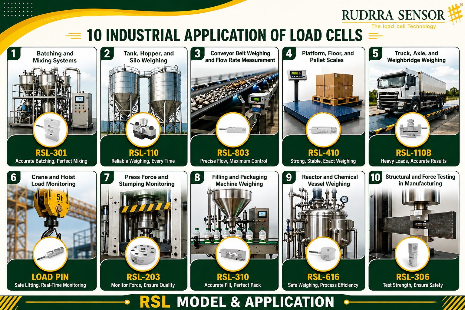
Walk through any manufacturing facility in the world — a food processing plant in Maharashtra, a steel mill in Jharkhand, a pharmaceutical factory in Hyderabad, a cement plant in Rajasthan, or an automobile assembly plant in Pune — and you will find load cells quietly at work. They sit beneath mixing vessels, under conveyor belt idlers, inside crane hook blocks, within hydraulic press platens, and under the legs of storage silos. Most people working in these facilities have never noticed them. Yet without them, virtually every automated weighing, batching, feeding, filling, and force monitoring operation in modern manufacturing would be impossible.
A load cell is a precision force sensor — a device that converts mechanical force into a proportional electrical signal that can be measured, displayed, recorded, and used to control a process. It is the physical realisation of the principle that mass and force are measurable with extraordinary precision, and that this measurement can be used to drive decisions and actions in automated manufacturing systems. Modern industrial load cells achieve measurement accuracies of 0.02% or better — meaning a load cell rated for 1,000 kg can distinguish between 999.8 kg and 1,000.0 kg — and maintain this accuracy reliably across years of continuous industrial operation.
This in-depth guide covers the top 10 industrial applications of load cells in manufacturing industries in comprehensive technical detail. For each application, we explain the underlying working principle, the most appropriate load cell types and specifications, the industry-specific requirements and challenges, and the concrete operational and financial benefits that load cell technology delivers. Whether you are an engineer specifying a new weighing system, a plant manager evaluating investment in measurement technology, or a procurement professional seeking to understand what you are buying, this guide provides the technical depth and practical context you need.
What Is a Load Cell? — A Technical Foundation
Before exploring specific industrial applications, it is worth establishing a clear technical understanding of what a load cell is and how it works — because this understanding directly informs the selection criteria for each application.
A load cell is a transducer: a device that converts one physical quantity into another that is more convenient to measure, transmit, and process. Specifically, a load cell converts a mechanical force (weight, tension, compression, or torque) into a proportional electrical signal. In the vast majority of industrial load cells, this conversion is achieved through the Wheatstone bridge strain gauge circuit.
The load cell’s core element is a precisely machined metal body — the spring element — typically made from high-strength alloy steel or stainless steel. Four strain gauges (thin foil resistive elements bonded to the spring element surface with high-performance adhesive) are positioned at locations on the spring element where mechanical strain — the fractional deformation under load — is greatest. When force is applied, the spring element deforms elastically (bending, stretching, or shearing, depending on the design), causing two of the strain gauges to stretch (increasing their resistance) and two to compress (decreasing their resistance). These four gauges form the four arms of a Wheatstone bridge circuit, powered by an excitation voltage of 5 to 12 volts. The bridge output — measured across the remaining two corners — is proportional to the applied force, typically in the range of 1 to 3 millivolts per volt of excitation at full rated load.
Key Load Cell Performance Parameters
Rated Output (RO): the nominal output at rated load, typically 1–3 mV/V. Non-linearity: maximum deviation of output from a straight line, expressed as % of RO. Hysteresis: difference between output on increasing and decreasing load, % of RO. Creep: change in output over time at constant load, % of RO. Temperature Effect on Zero: change in zero output per 10°C temperature change. IP Rating: degree of sealing against dust and water ingress (IP67 = dust-tight, 30-minute immersion). OIML Class: accuracy classification (C1 to C6) under the International Organisation of Legal Metrology.
| ±0.02%
Typical accuracy of C3 class load cell |
IP68
Highest sealing for submersible use |
300%
Typical ultimate overload rating |
10M+
Fatigue cycles for rated load cells |
The Load Cell Market in Indian Manufacturing — Context and Growth
India’s manufacturing sector is in a period of transformational growth, driven by the government’s Make in India initiative, the Production Linked Incentive (PLI) schemes across 14 key sectors, and the accelerating shift towards Industry 4.0 and smart manufacturing. Load cells sit at the intersection of these trends: as manufacturing plants become more automated, more data-driven, and more precision-oriented, the demand for accurate, reliable, digitally connected force measurement grows in step.
The Indian load cell and weighing sensor market has grown consistently at 8–12% per year over the past decade, driven by expansion in food processing, pharmaceuticals, chemicals, logistics, and heavy industry. The adoption of GST and e-Way Bill regulations has further driven demand for accurate vehicle and freight weighing. Growing export orientation of Indian manufacturers — particularly in automotive, pharmaceuticals, and specialty chemicals — is raising quality standards to international levels, requiring the precision force measurement that only quality load cells can provide.
Rudrra Sensor, founded in Ahmedabad in 2002, has been a part of this growth story — supplying precision load cells, indicators, amplifiers, and weighing system solutions to industrial customers across India and to international markets for over two decades. Our product range addresses every major industrial application discussed in this guide, with technical expertise to help customers specify, install, and maintain the right load cell solution for their exact requirements.
Quick Reference: Top 10 Load Cell Applications at a Glance
| # | Application | Key Industry | Best Load Cell | Primary Benefit |
| #1 | Batching & Mixing Systems | Food, Chemical, Pharma, Plastics | S Type / Compression LC | Ingredient accuracy to 0.1%; reduces waste and rework |
| #2 | Tank, Hopper & Silo Weighing | Chemical, Agriculture, Food & Bev | Compression / S Type LC | Real-time inventory; replaces manual level gauging |
| #3 | Conveyor Belt Weighing | Mining, Cement, Steel, Aggregate | Shear Beam LC | Continuous mass flow rate and cumulative tonnage |
| #4 | Platform & Floor Scales | Logistics, Warehousing, Mfg | Shear Beam / Single Point LC | Fast goods-in/out weighing; ERP integration |
| #5 | Truck & Weighbridge Weighing | Transport, Mining, Agriculture | Beam Type / Compression LC | Legal-for-trade; overload prevention; payload control |
| #6 | Crane & Hoist Load Monitoring | Steel, Shipbuilding, Heavy Eng. | S Type / Load Pin LC | Overload prevention; real-time cab display; safety |
| #7 | Press Force & Stamping Monitor | Automotive, Metal Forming, Forging | Pan Cake / Compression LC | Tool protection; SPC force signatures; scrap reduction |
| #8 | Filling & Packaging Machines | FMCG, Pharma, Food & Bev | Single Point / S Type LC | Eliminates giveaway; check-weighing compliance |
| #9 | Reactor & Vessel Weighing | Chemical, Pharma, Petrochemical | Compression / Shear Beam LC | Precise reactant addition; GMP batch records |
| #10 | Structural & Force Testing | Aerospace, Automotive, Civil Eng. | S Type / Pan Cake / Load Pin | Material characterisation; certification testing |
Batching and Mixing Systems
Industry: Food Processing, Chemical Manufacturing, Pharmaceuticals, Plastics | Recommended Load Cell: S Type Load Cell / Compression Load Cell
Overview and Importance
Batching is one of the oldest and most fundamental operations in manufacturing — and yet it remains one of the most technologically demanding. Whether the end product is a chocolate bar, a batch of polymer resin, a pharmaceutical tablet, or a can of industrial paint, the consistency and quality of the final product depends entirely on the accuracy with which its constituent raw materials are measured and combined. Even a deviation of a fraction of a percent in a critical ingredient can alter taste, viscosity, potency, colour, or structural properties — making precise batching an absolute operational requirement rather than a mere convenience.
Load cells have replaced volumetric measurement and manual weighing as the primary technology for batching in modern manufacturing. Their ability to provide continuous, real-time weight feedback — accurate to 0.01% of the rated output or better — combined with direct interfacing with PLC and batch management systems, makes them uniquely suited to the demands of automated batching operations at industrial scale.
How Load Cell Batching Systems Work
There are two fundamental approaches to load cell-based batching: gain-in-weight and loss-in-weight. Understanding the difference is critical to selecting the right architecture for a given application.
In a gain-in-weight batching system, the mixing vessel or weigh hopper sits on load cells. As ingredients are added — either manually or through automated feeders, pumps, and valves — the total weight of the vessel increases. The PLC monitors the weight signal continuously and triggers the closure of feed valves or the stop of conveyors when the target weight is reached. This approach is well-suited to applications where multiple ingredients are added sequentially into a single vessel, as each addition is independently confirmed by the load cell before proceeding.
In a loss-in-weight batching system, the supply hopper or raw material container sits on load cells. As material is dispensed from the hopper into the process, the weight of the supply container decreases. The batch management system calculates the dispensed weight as the difference between the starting weight and the current weight. Loss-in-weight systems are particularly valuable for continuous processing applications, where material must be dispensed at a controlled, consistent mass flow rate — for example, feeding raw ingredients to a continuous mixer or extruder at a precise rate of kilograms per hour.
Industry-Specific Applications
Food and Beverage Manufacturing
In food manufacturing, a single product recipe may call for precise quantities of dozens of ingredients — flours, sugars, fats, flavourings, leavening agents, preservatives, colourings, and more — each in amounts that must be correct to within fractions of a percentage point. A commercial bread manufacturer, for instance, producing thousands of loaves per shift, uses load cell-based batching systems to automatically weigh each ingredient before mixing, with tolerances as tight as ±0.1% on critical ingredients. Even a small shortfall in leavening agent across a batch of 2,000 loaves can result in product rejection and significant financial loss.
The food industry also presents unique environmental demands: load cells in food processing must be constructed of food-grade stainless steel, carry IP67 or higher ingress protection ratings for wash-down compatibility, and comply with hygienic design standards that prevent the accumulation of product residue. Rudrra Sensor manufactures stainless steel S type and compression load cells specifically designed for food-grade batching environments.
Pharmaceutical Manufacturing
In pharmaceutical batching, the stakes are higher still. Regulatory frameworks including the US FDA’s Current Good Manufacturing Practice (cGMP) and India’s Schedule M require that every ingredient in every batch be weighed to a documented accuracy, with full electronic traceability. A single batch of a pharmaceutical formulation may represent hundreds of thousands of rupees in active pharmaceutical ingredients — making the cost of a batching error catastrophic. Load cells in pharmaceutical batching systems provide the accuracy (often to four decimal places for small batches), the electronic data logging, and the audit trail required by regulatory inspectors.
Chemical and Polymer Manufacturing
In chemical plants, precise batching is essential both for product consistency and for safety. Many chemical reactions are exothermic — adding too much of a reactant can trigger an uncontrolled temperature rise. Load cells enable the controlled, metered addition of reactants to mixing vessels, with the weight signal feeding directly into the distributed control system (DCS) that manages the entire reaction process. In polymer manufacturing, precise measurement of catalyst, monomer, and additive quantities directly determines the molecular weight and physical properties of the final polymer product.
Technical Specification for Batching Load Cells
| Parameter | Details |
| Recommended Type | S Type (tension/compression) for hanging hoppers; Compression/button for vessel supports |
| Capacity Range | 5 kg to 5,000 kg depending on vessel size and batch weight |
| Accuracy Class | OIML C3 or higher for pharmaceutical; C2 acceptable for general food/chemical batching |
| Material | Stainless steel (AISI 304/316) for food, pharma, and chemical; alloy steel for plastics/non-contact |
| IP Rating | IP67 minimum for food/pharma; IP68 for continuous immersion or high-pressure wash-down |
| Output Signal | mV/V for standard systems; 4-20 mA or digital for long cable runs or smart controllers |
| Temperature Range | -10°C to +70°C compensated for standard environments; extended range for oven/freezer applications |
| Typical Accuracy | ±0.02% to ±0.05% of rated output depending on class and installation quality |
Key Benefits of Load Cell Batching
- Ingredient accuracy within 0.01% to 0.1% of target weight depending on system design — far superior to volumetric methods
- Fully automated batching eliminates manual weighing errors and reduces reliance on skilled labour
- Real-time weight feedback enables immediate correction if a feed valve is slow or a pump under-delivers
- Electronic batch records provide complete traceability for quality audits, customer disputes, and regulatory inspections
- Reduction in raw material waste — in high-value ingredients such as food flavourings, pharmaceuticals, or specialty chemicals, even 0.1% waste reduction translates to significant annual cost savings
- Compatibility with loss-in-weight feeding systems enables precise continuous mass flow control for extruders, mixers, and reactors
- Hygienic stainless steel designs meet food and pharmaceutical regulatory requirements without compromise
Tank, Hopper, and Silo Weighing
Industry: Chemical Processing, Agriculture, Food & Beverage, Plastics, Water Treatment | Recommended Load Cell: Compression Load Cell / S Type Load Cell
Overview and Importance
Every manufacturing facility that processes or stores bulk materials — whether liquids, powders, granules, or bulk solids — needs to know how much material it has at any given moment. This inventory knowledge drives production planning, purchasing decisions, safety management, and billing. Traditionally, this information was obtained through sight glasses, level probes, ultrasonic sensors, or manual dipping — all of which have significant limitations in accuracy, reliability, or suitability for the wide variety of materials and conditions found in industrial environments.
Load cell-based weighing of tanks, hoppers, and silos has become the preferred solution for bulk inventory management across virtually every process industry. By mounting load cells under or around the storage vessel, the actual weight of vessel contents is measured continuously and accurately, regardless of the density, viscosity, temperature, or surface characteristics of the material — limitations that challenge every level-based measurement technology.
System Architecture and Installation Principles
A typical tank weighing installation uses three or four compression load cells, positioned under the legs or mounting feet of the vessel. The exact number depends on vessel geometry: three-legged vessels naturally use three load cells (one per leg); four-legged vessels use four. The choice of three versus four cells is a significant engineering consideration — a three-point support is inherently statically determinate (all load cells share load equally regardless of minor structural variation), while a four-point installation requires careful attention to structural stiffness to ensure consistent load sharing.
Each load cell is connected to a load cell junction box, where the individual cell outputs are summed. In a well-installed system, each load cell carries an equal share of the total vessel weight, and the junction box may include trimming resistors to compensate for minor sensitivity differences between cells. The summed output from the junction box feeds a digital weight indicator or PLC analogue input, which displays and records the vessel weight in real time.
The mechanical mounting hardware is as critical as the load cell itself in achieving accuracy. Cup-and-ball mounting assemblies, rocker pins, or load buttons — all designed to transmit pure compressive force along the load cell axis while accommodating minor structural deflection — are essential for long-term stability and measurement accuracy. Any rigid structural connection to the vessel that provides an alternative load path will compromise accuracy and cause the system to drift over time.
Silo Weighing in Bulk Material Industries
In grain handling, cement production, plastics manufacturing, and bulk chemical storage, multiple silos of varying sizes and contents must be monitored simultaneously. A large grain handling facility may have dozens of silos, each holding thousands of tonnes of different grain varieties, with constant inflow from trucks and trains and outflow to processing equipment. Load cell-based silo weighing provides real-time inventory data for every silo on a single SCADA screen, enabling operators to manage the entire facility’s inventory with a level of accuracy and convenience that manual or probe-based methods simply cannot match.
Silo weighing also enables accurate measurement of material consumption rates — critical for production scheduling and raw material purchasing. If a silo of raw polymer pellets is losing weight at a rate of 500 kg per hour, the production planning system can calculate exactly when it will need to be replenished and trigger an automatic purchase order — long before the silo runs empty and production is disrupted.
Challenging Liquid Applications
Tank weighing for liquid storage presents particular challenges. Liquids exert hydrostatic pressure on the vessel walls, and the vessel itself flexes slightly under load. Rigid pipework connections to the tank create parallel load paths that bypass the load cells, introducing systematic measurement errors. For accurate liquid tank weighing, all process pipe connections must use flexible hose sections or expansion joints at the tank connection point, allowing the tank to deflect freely on its load cells without being constrained by the pipework.
Agitators, mixers, and heating elements inside tanks impose additional dynamic forces on the load cells. In applications with mechanical agitation, load cells must have sufficient dynamic rating to handle the cyclic loading from the agitator, and signal filtering must be applied in the indicator to smooth out vibration-induced noise.
Technical Specification for Tank/Silo Load Cells
| Parameter | Details |
| Recommended Type | Compression load cells for vessel support legs; S Type for tension mounting (hanging vessels) |
| Capacity Range | 500 kg to 500,000 kg per load cell depending on vessel size; sets of 3-4 cells |
| Number of Cells | 3 cells for three-legged vessels; 4 cells for four-legged or rectangular vessels |
| Material | Stainless steel for food, chemical, outdoor; alloy steel for dry indoor environments |
| IP Rating | IP67 minimum; IP68 for vessels in wash-down areas or outdoors |
| Mounting Hardware | Cup-and-ball assemblies, rocker pins, or self-aligning load buttons essential |
| Process Connections | All pipe connections must use flexible hose or expansion joints at vessel |
| Accuracy Class | C2 for general inventory; C3 for custody transfer and billing applications |
Key Benefits of Load Cell Tank and Silo Weighing
- True weight measurement independent of material density, temperature, level, or surface conditions — works with materials that defeat level-based sensors
- Real-time inventory visibility across multiple vessels from a central SCADA or ERP system
- Automated low-level alarms and high-level alarms prevent stockouts and overflows without manual monitoring
- Accurate measurement of material consumption rates supports production planning and procurement
- Eliminates hazardous manual dipping of tanks containing chemicals, solvents, or hot materials
- Accurate custody transfer measurement of incoming deliveries from tanker trucks or rail cars
- No moving parts in contact with the process material — load cells measure externally, offering exceptional reliability and low maintenance
Conveyor Belt Weighing and Flow Rate Measurement
Industry: Mining, Cement, Steel Manufacturing, Coal Handling, Aggregate Quarrying | Recommended Load Cell: Shear Beam Load Cell
Overview and Importance
In industries that process bulk materials continuously at large scale — coal mining, iron ore beneficiation, cement clinker production, limestone quarrying, and steel manufacturing — the ability to accurately measure how much material is being transported on a conveyor belt at any given moment is a fundamental operational and commercial requirement. Conveyor belt scales, also known as belt weighers or weightometers, are the industry-standard solution, and shear beam load cells are the heart of every belt scale installation.
The scale of these operations makes even small measurement errors commercially significant. A belt conveyor handling 1,000 tonnes per hour that has a 0.5% measurement error is incorrectly accounting for 5 tonnes per hour — 120 tonnes per day, or over 40,000 tonnes per year. At any realistic commodity price, this represents a substantial financial discrepancy between buyer and seller. For this reason, conveyor belt scales used for custody transfer and billing must meet stringent national and international accuracy standards, and their load cells must be of the highest quality.
How Belt Scale Systems Function
A conveyor belt scale consists of three primary components working together: one or more weigh idler frames mounted on load cells within the conveyor structure, a belt speed sensor (typically a tachometer or pulse encoder on an idler or the drive pulley), and an integrating totaliser/controller that combines the weight and speed signals to compute mass flow and cumulative total.
The weigh idler frame replaces a standard idler frame in the conveyor structure. One, two, or more conveyor belt idler rollers are mounted on this frame, which in turn sits on one or two shear beam load cells. As material-laden belt passes over the weigh idler, the downward force — the weight of the belt and material on a defined section — is measured by the load cells. The weight per unit length of belt, multiplied by the belt speed, gives the instantaneous mass flow rate in tonnes per hour. Integrating this flow rate over time gives the cumulative total tonnage conveyed.
Why Shear Beam Load Cells Excel in Belt Scale Applications
Shear beam load cells are the universal choice for conveyor belt weighing, and for compelling technical reasons. The mechanical environment of a moving conveyor is inherently imperfect — belt tension variations, material impact at the loading point, and structural flex all create forces that are not purely downward. A shear beam load cell’s response to off-axis forces and bending moments is very low, making it inherently immune to the side forces and moments that would corrupt the measurement of other load cell types.
Shear beam load cells also offer high overload capacity — typically 150% to 300% of rated load — which is essential in conveyor applications where a sudden large lump of rock or a surge of material from a blocked chute can momentarily impose several times the normal load on the weigh frame. The robust, sealed construction of industrial shear beam load cells allows them to operate reliably for years in the harsh conditions of mining and quarrying — high dust, moisture, vibration, and temperature variation.
Multi-Idler Belt Scale Designs for High Accuracy
Single-idler belt scales are the most common and economical design, suitable for general inventory and process control applications with accuracy requirements of ±0.5% to ±1%. For higher accuracy — required for custody transfer and billing — multi-idler belt scales use two, three, or four weigh idlers, effectively increasing the weighing length and averaging out the effect of belt tension variations and belt splice irregularities. A four-idler belt scale can achieve accuracy of ±0.25% or better under favourable installation conditions.
Installation quality is as important as the load cell specification in achieving belt scale accuracy. The approach run of conveyor (the length of unloaded belt before the weigh idler) and the leave run (the length after) must be sufficient to allow the belt to stabilise between the loading point and the weigh frame. Ideally, the approach run should be at least 10 metres and the leave run at least 3 metres. The conveyor structure near the weigh frame must be rigid — any structural flex under load introduces a systematic error. Idler spacing before and after the weigh frame must match the weigh frame idler spacing exactly.
Integration with Plant Control and Billing Systems
Modern belt scale controllers offer extensive connectivity for integration with plant automation, SCADA systems, and ERP platforms. Real-time flow rate data can feed automatically into production control systems that adjust feed rates, blend ratios, or stockpile management strategies. Cumulative totaliser data feeds directly into billing and inventory management systems, creating automated, auditable records of material movements without the need for manual data entry.
In coal and ore blending applications, multiple belt scales on parallel or series conveyors allow precise control of blending ratios. By adjusting the feed rate from each conveyor in response to the belt scale output, the blend controller can maintain a target ratio of different material grades with high precision — a capability that directly impacts the quality and commercial value of the blended product.
Technical Specification for Conveyor Belt Scale Load Cells
| Parameter | Details |
| Recommended Type | Shear beam load cell (low-profile or standard profile depending on idler height) |
| Capacity Range | 50 kg to 5,000 kg per load cell depending on belt width and material density |
| Number of Cells | 2 cells per weigh idler frame (one each side of the frame) |
| IP Rating | IP67 minimum; IP68 for outdoor or high-washdown applications |
| Accuracy Class | OIML C3 for custody transfer; C2 for process control and inventory |
| Dynamic Rating | Must be rated for continuous dynamic loading — specify ‘fatigue-rated’ where available |
| Cable | Shielded, armoured cable; minimum 5 metres from load cell to avoid cable flex at load cell |
| Vibration Resistance | Essential — specify load cells tested to relevant vibration standards for conveyor applications |
Key Benefits of Conveyor Belt Load Cell Weighing
- Continuous, non-intrusive measurement of bulk material flow with no contact with the product stream
- Accurate billing and custody transfer — meeting OIML and national weights and measures requirements
- Real-time flow rate control enables precise blending of multiple material streams
- Integration with plant automation systems supports fully automatic material management
- No moving parts in contact with the material — minimal maintenance and wear compared to alternative measurement methods
- Early detection of conveyor overloading protects mechanical components and prevents structural damage
- Historical flow data supports production analysis, energy efficiency improvement, and asset management
Platform, Floor, and Pallet Scales
Industry: Logistics, Warehousing, Manufacturing, Quality Control | Recommended Load Cell: Shear Beam Load Cell / Single Point Load Cell
Overview and Importance
If there is one weighing application that touches virtually every manufacturing and logistics operation, it is the platform scale. Platform and floor scales appear at every material handling touchpoint — goods-in receiving docks, outbound dispatch bays, production floors, quality control laboratories, packing stations, and warehouses. They are the workhorses of industrial weighing, used hundreds or thousands of times daily to weigh everything from small components and retail cartons to heavy pallets and bulk containers.
The ubiquity of platform scales makes their accuracy and reliability business-critical. Inaccurate weighing at goods-in means overpaying for material. Inaccurate weighing at dispatch means incorrect freight billing — either overcharging customers or absorbing excess freight costs. In quality control, inaccurate component weighing can pass defective parts or reject acceptable ones. The cumulative financial impact of even small systematic weighing errors across thousands of transactions per year is substantial.
Shear Beam vs Single Point Load Cells in Platform Scales
The choice between shear beam and single point load cells for platform scales depends primarily on platform size and capacity. For larger platforms — floor scales, pallet scales, and industrial platform scales — four shear beam load cells, positioned at the corners of a steel frame, are the standard solution. Each load cell carries approximately one quarter of the platform load, and their outputs are summed in a junction box. This architecture is inherently robust, capable of handling capacities from a few hundred kilograms to 10 tonnes or more, and is excellent at handling off-centre loads and accidental overloads.
For smaller platforms — bench scales, retail scales, postal scales, counting scales, and laboratory scales — a single single-point load cell is the preferred design. A single-point load cell is a specially designed beam element that delivers accurate weight measurement regardless of where the load is placed on the platform. This is achieved through a combination of the load cell geometry and precision machining tolerances that make the sensitivity uniform across the entire platform surface. A single load cell supporting the entire platform simplifies installation dramatically and reduces cost.
Counting Scales and Component Verification
A particularly important specialisation of platform scale technology in manufacturing is the counting scale. A counting scale uses a high-resolution load cell to determine the weight of a single component (the ‘unit weight’), then automatically calculates the number of identical components on the platform by dividing the total platform weight by the unit weight. This allows rapid, accurate counting of large quantities of small components — nuts, bolts, washers, electronic components, packaged goods — at a fraction of the time required for manual counting.
In manufacturing operations that manage component inventories — particularly automotive parts suppliers, electronics manufacturers, and packaging operations — counting scales with load cells of 0.1 gram or better resolution are used to verify component quantities for kitting, shipping, and inventory management. The accuracy of the count depends directly on the accuracy and resolution of the load cell, making high-quality load cell selection critical for this application.
Integration with ERP and Warehouse Management Systems
Modern industrial platform scales are increasingly connected to factory ERP systems, warehouse management systems (WMS), and logistics platforms through digital interfaces. When a pallet arrives at a goods-in dock, the platform scale automatically captures the gross weight, which is transmitted to the WMS along with the scan of the barcode or RFID tag on the pallet. The WMS calculates the net weight by subtracting the known pallet weight, checks this against the expected delivery quantity, and either accepts or flags the delivery for manual review — all without any manual data entry.
Similarly, at dispatch, automated weighing integrated with the WMS ensures that every outbound shipment is weighed, the weight is recorded against the shipment record, and any discrepancy from the expected weight triggers an alert before the shipment leaves the facility. This end-to-end weight capture creates a complete audit trail for every material movement, supporting compliance with customer requirements, customs regulations, and internal quality standards.
Technical Specification for Platform and Floor Scale Load Cells
| Parameter | Details |
| Recommended Type | Shear beam (4 cells) for platform scales >100 kg; single point (1 cell) for small platforms |
| Capacity Range | 1 kg to 10,000 kg; select with 20-30% safety margin over maximum expected load |
| Accuracy | 0.01% to 0.05% of full scale depending on class; high-resolution for counting applications |
| IP Rating | IP65 for dry warehouse/indoor; IP67 for outdoor or food/wash-down environments |
| Material | Alloy steel for general industrial; stainless steel for food/pharmaceutical/outdoor |
| Output | mV/V standard; consider digital output for direct PLC or ERP connection |
| Overload Capacity | Shear beam: 150-300% of rated; important for forklift traffic on floor scales |
| Platform Integration | Must use matched platform frame, summing junction box, and matched indicator |
Key Benefits of Platform and Floor Scale Load Cells
- Fast, accurate weighing at every goods movement touchpoint reduces billing errors and inventory discrepancies
- High overload protection handles the inevitable accidental overloads of forklift operation and pallet drops
- Digital connectivity eliminates manual data entry errors and accelerates throughput at weighing stations
- Wide capacity range — from gram-resolution counting scales to 10-tonne floor scales — from a single technology
- Single-point load cell design enables accurate off-centre load measurement without complex four-cell installation
- Stainless steel and IP67 variants available for food, pharmaceutical, and outdoor applications
- Easy recalibration in situ using certified test weights, maintaining accuracy without removing from service
Truck, Axle, and Weighbridge Weighing
Industry: Road Transport, Mining, Agriculture, Construction, Port Operations | Recommended Load Cell: Beam Type Load Cell / Compression Load Cell
Overview and Importance
The measurement of vehicle weights has been a legal requirement in India and globally for decades, driven by the twin imperatives of protecting road infrastructure from overloading damage and ensuring fair commercial measurement in bulk commodity trading. A truck weighbridge is the defining piece of infrastructure for this purpose — and at its heart, a set of precision load cells provides the measurement capability that makes accurate, legally defensible vehicle weighing possible.
The scale of operation of truck weighbridges in Indian industry is considerable. A single weighbridge at a cement plant, steel mill, or grain handling depot may process hundreds of trucks per day, each carrying loads of 20 to 30 tonnes. The cumulative weight of material measured and billed through that weighbridge in a year runs to millions of tonnes. An accuracy error of even 0.1% at such volumes represents thousands of tonnes of material measured incorrectly — a commercial, regulatory, and reputational problem of the first order.
Construction and Load Cell Arrangement
A standard truck weighbridge consists of a structural steel or reinforced concrete deck, supported on multiple load cells positioned in pits below grade level. The deck is typically 18 to 20 metres long (to accommodate a fully laden articulated truck) and 3 to 3.5 metres wide. Load cells are positioned under the longitudinal stringers of the deck, at intervals of approximately 3 to 4 metres along the length, giving a total of 6 to 8 load cells per weighbridge depending on capacity and length.
The load cells used in truck weighbridges are typically beam type or compression type, selected for their very high capacity (rated loads of 20 to 50 tonnes per cell are common), extreme overload resistance, and robustness against the dynamic impact loading that occurs as a heavily laden truck drives onto and across the bridge. The load cell mounting hardware must be designed to allow the deck to deflect slightly under load without imposing bending moments on the load cells — self-aligning mounting systems that accommodate minor angular misalignment while transmitting only vertical (compressive) force to the load cell are the engineering-preferred solution.
Axle Weighing and Weigh-in-Motion
Beyond static weighbridge weighing, two specialised variants of vehicle weighing technology address specific operational needs. Axle weighers are single-axle or tandem-axle platforms, typically 1.5 to 2 metres long, used to weigh individual axle groups as the truck drives slowly across them. By summing the axle weights, the gross vehicle weight is determined. More importantly, axle weighers can identify which axle group is overloaded even when the gross weight is within the legal limit — a capability that static weighbridges cannot provide and that is essential for enforcement of axle load limits.
Weigh-in-motion (WIM) systems represent the most technologically advanced form of vehicle weighing. WIM sensors — typically quartz piezoelectric sensors or load cell-based systems — are embedded in the road surface and measure axle loads as vehicles pass at normal traffic speed, without requiring the vehicle to slow down or stop. WIM systems are primarily used for traffic management, pavement design data collection, and pre-selection of overloaded vehicles for static re-weighing. They represent one of the most demanding load cell applications, requiring sensors that respond accurately to transient dynamic loads of millisecond duration.
Payload Monitoring in Mining and Construction
In mining, quarrying, and earthworks operations, a different form of vehicle weighing is used: onboard payload monitoring systems fitted to dump trucks, loaders, and excavators. Load cells or strain gauge-based sensors integrated into the vehicle’s suspension or hydraulic systems measure the payload in the truck body during loading, allowing the operator and the dispatch system to know the payload in real time — without driving to a fixed weighbridge.
Accurate payload monitoring directly improves the productivity and profitability of mining operations. A truck loaded to exactly its rated payload on every trip maximises material movement per truck per shift. A truck loaded under capacity wastes trip potential; a truck overloaded risks tyre, suspension, and structural damage that leads to costly unplanned maintenance. Load cell-based payload systems — either onboard or at fixed load-out stations — enable the discipline of ‘one-pass loading’ that maximises productivity while protecting the equipment.
Automated Weighbridge Systems and Integration
Modern truck weighbridges are fully automated systems, integrating load cells with camera-based automatic number plate recognition (ANPR), RFID vehicle identification, traffic light control systems, automatic barriers, and comprehensive weighbridge management software. A driver arriving at an automated weighbridge is identified by ANPR or RFID tag, drives forward onto the bridge on a green light, the gross weight is measured and compared with the tare weight stored in the system database, and a weighbridge ticket is automatically printed — without any operator involvement. This automation dramatically increases throughput, eliminates transcription errors, and provides a complete, tamper-proof audit trail of every weighing transaction.
Technical Specification for Weighbridge Load Cells
| Parameter | Details |
| Recommended Type | Beam type or double-ended shear beam for bridge deck loading; compression for pit-mounted |
| Capacity Range | 20 to 50 tonnes per load cell; 6-8 cells per full-length weighbridge |
| Accuracy Class | OIML C3 mandatory for legal-for-trade weighbridges; C4 for highest accuracy applications |
| IP Rating | IP68 minimum — load cells in bridge pits are exposed to ground water and flooding |
| Material | Stainless steel recommended for long service life in outdoor, below-grade environments |
| Cable | Armoured, waterproof cable; minimum 10 metres to junction box to prevent moisture tracking |
| Overload | Safe overload 150%; ultimate overload 300% minimum — essential for dynamic truck loading |
| Certification | Must carry pattern approval certificate from Weights & Measures authority for legal trade |
Key Benefits of Load Cell Weighbridge Systems
- Legal-for-trade accuracy for commodity billing in grain, cement, steel, coal, and bulk chemical trading
- Prevention of road infrastructure damage through enforcement of legal axle and gross vehicle weight limits
- Full automation eliminates operator error, speeds throughput, and creates tamper-proof transaction records
- Payload optimisation in mining operations reduces cost-per-tonne and extends equipment life
- Integration with ERP and commodity trading systems enables automatic generation of billing documents
- Remote monitoring of weighbridge performance and load cell health enables predictive maintenance
Crane and Hoist Load Monitoring
Industry: Steel Manufacturing, Shipbuilding, Construction, Heavy Engineering, Ports | Recommended Load Cell: S Type Load Cell / Load Pin Load Cell
Overview and Importance
Crane and hoist overloading is one of the most serious safety hazards in heavy manufacturing and construction. When a crane lifts a load that exceeds its rated capacity, the consequences can be catastrophic: structural failure of the crane boom or bridge, collapse of the load, and potentially fatal injuries to workers in the area. According to safety data from major industrial sectors, crane accidents cause hundreds of fatalities and thousands of injuries worldwide each year, with overloading being a primary contributing factor in a significant proportion of these incidents.
Load cells integrated into crane and hoist systems provide the first line of defence against overloading: continuous, real-time measurement of the actual lift force. This is not a design estimate, not an operator’s visual judgement, and not a retrospective calculation — it is the precise weight of the load being lifted, displayed in the operator’s cab as the lift is made, and compared automatically against the crane’s rated capacity to trigger warnings and cut-outs before a safe limit is reached.
Load Cell Types for Crane Applications
S type load cells and load pin load cells are the two dominant types used in crane and hoist load monitoring, each with distinct installation advantages.
S type load cells (also called S beam load cells) are typically installed in tension — placed in the lifting line between the crane hook block and the crane structure, or in the rope termination. They measure the tension in the lifting line, which directly equals the weight of the suspended load (accounting for multiple-part reeving factors). S type cells are available in capacities from 500 kg to 100 tonnes or more, and offer high accuracy, robust construction, and compatibility with standard swivel and shackle fittings.
Load pin load cells (also known as load shackles or instrumented pins) offer an even more elegant solution. They are manufactured as a direct dimensional replacement for the structural pin in the crane’s hook block, equaliser beam, or sheave assembly. Because they are the same size and shape as the original structural pin, no modification to the crane structure is required — the original pin is simply removed and the instrumented load pin inserted in its place. This ‘bolt-in’ approach minimises installation time and disruption, making load pin load cells the preferred solution for retrofitting load monitoring to existing cranes.
Overload Protection and Safety Systems
A complete crane load monitoring system comprises the load cell (S type or load pin), a signal conditioner or telemetry unit (wireless transmission is common in crane applications to eliminate trailing cables), and a cab-mounted display and alarm controller. The controller continuously compares the measured load against programmable thresholds:
- Pre-warning alarm (typically at 90% of rated load): audible and visual warning to the operator that the load is approaching the safe working limit
- Warning alarm (at 100% of rated load): more urgent audible and visual alarm indicating the rated load has been reached
- Cut-out (at 110% of rated load): automatic inhibition of the ‘lift’ function, preventing further load from being applied; the operator retains full control of lowering
In complex lifting operations involving multiple cranes sharing a load (tandem lifts), load cells on each crane provide real-time data on load sharing — essential information for the lift supervisor to manage the operation safely and to detect any unexpected load redistribution that could overload one crane while the other takes less than its share.
Wireless Telemetry for Crane Load Cells
In overhead crane applications — bridge cranes, gantry cranes, and portal cranes — a trailing cable from the load cell to the cab display is impractical and a potential operational hazard. Wireless telemetry systems, using load cell transmitter units that clip onto the lifting rigging and transmit the load signal via RF to a cab-mounted receiver display, solve this problem elegantly. The transmitter unit is typically battery-powered, with battery life of several thousand hours, and is designed to withstand the mechanical abuse of crane rigging environments.
Load Data Logging for Compliance
Beyond real-time safety monitoring, load cell data logging systems record the weight of every lift performed by the crane — time-stamped, with the peak load reached and the duration. This data is invaluable for regulatory compliance (lifting equipment regulations in India and internationally require that cranes are not operated beyond their rated capacity), insurance purposes (demonstrating that the crane has been operated within its design envelope), and structural life management (tracking the crane’s load history for fatigue life calculation).
Technical Specification for Crane Load Monitoring
| Parameter | Details |
| Recommended Type | S Type LC for lifting line; Load Pin LC for direct structural replacement |
| Capacity Range | 500 kg to 500 tonnes depending on crane SWL |
| Accuracy | ±0.1% to ±0.5% of full scale — sufficient for safety monitoring; higher accuracy for certified weighing |
| Transmission | Wireless (RF) for overhead cranes; wired for fixed hoists and derricks |
| Display | Cab-mounted digital display with load percentage bar graph and alarm indicators |
| Data Logging | Automatic logging of peak load and duration for every lift cycle |
| Power Supply | Self-contained battery in transmitter; 5+ year life at typical duty cycle |
| Certification | Must comply with relevant lifting equipment safety standards (IS, EN, ASME as applicable) |
Key Benefits of Load Cell Crane Monitoring
- Prevents crane overloading — the primary cause of crane structural failure and associated fatalities
- Real-time cab display gives operators continuous load awareness during every lift
- Automatic lift cut-out at rated capacity provides a safety backstop independent of operator judgement
- Wireless telemetry eliminates trailing cables in overhead crane applications
- Load data logging supports regulatory compliance and structural life management
- Load pin design requires no structural modification — rapid retrofit to existing cranes
- Tandem lift coordination improves safety in complex multi-crane operations
Press Force and Stamping Monitoring
Industry: Automotive Manufacturing, Metal Forming, Forging, Plastics, Powder Metallurgy | Recommended Load Cell: Pan Cake Load Cell / Compression Load Cell
Overview and Importance
Industrial presses — whether mechanical stamping presses, hydraulic forming presses, forging presses, injection moulding machines, or powder compaction presses — are among the most capital-intensive and operationally critical pieces of equipment in manufacturing. A large automotive stamping press can cost several crores of rupees; the dies and tooling it uses may cost lakhs each. Protecting this investment while maintaining consistent product quality requires precise monitoring and control of the force applied during each press stroke — a role perfectly suited to load cell technology.
Press force monitoring with load cells serves two distinct but equally important purposes: protection and quality assurance. From a protection perspective, load cells detect abnormal force levels that indicate a foreign object in the die, a misaligned blank, or a tooling problem before mechanical damage occurs. From a quality perspective, the force-displacement signature of each press stroke provides a fingerprint of the forming process — a window into whether the material, tooling, and process conditions are correct for every single part produced.
Load Cell Integration in Press Systems
Pan cake load cells are the preferred choice for press force monitoring, and their mechanical characteristics explain why. Their extremely flat, disc-like profile — typically 25 to 50 mm high for capacities of 100 to 5,000 kN — allows them to be integrated into the press structure with minimal modification. In a typical installation, the load cell is placed between the press bed plate and the die shoe, or between the slide (ram) and the upper die holder. During each press stroke, the forming force passes through the load cell, generating a real-time force signal.
In a multi-point installation — increasingly common in large-tonnage presses — four load cells are placed at the corners of the die area. This arrangement measures not just the total press force but also the distribution of force across the die. Uneven force distribution indicates a tipping moment on the press slide, which can cause premature die wear, slide guide wear, and dimensional errors in the formed part. By monitoring the four corner forces, the press operator can detect and correct this condition before damage accumulates.
Statistical Process Control Using Force Signatures
In automotive stamping plants and other high-volume manufacturing operations, the force signature of the press stroke — the time-history of force during a complete stroke cycle, from initial contact to full depth and return — is captured for every part. Advanced press monitoring systems compare this signature against a reference waveform captured during a qualified production run. Significant deviations from the reference signature — in peak force, timing, shape, or energy — are flagged as potential quality issues and the press can be automatically stopped for inspection.
This approach, known as force signature monitoring or process signature monitoring, is a form of Statistical Process Control (SPC) that operates in real time, 100% of production, rather than relying on periodic sampling. It can detect worn or broken tooling, incorrect material grade or thickness, misaligned blanks, contamination in the die, and a host of other process anomalies — often before they result in an out-of-specification part leaving the press. In automotive manufacturing, where supplier quality requirements (IATF 16949) demand 100% traceability and zero defects, this capability is increasingly mandatory rather than optional.
Forging and High-Energy Press Applications
In forging — where hot metal billets are formed under very high forces using hammers or presses — the demands on load cell technology are extreme. Forging presses generate forces of hundreds of MN, with very rapid load application rates and high temperatures near the die. High-capacity pan cake load cells, integrated into the press tie-rod structure or press frame, monitor the forging force to ensure each blow delivers the correct energy to achieve the required grain structure and dimensional accuracy in the forged part.
Powder metallurgy compaction presses represent another demanding application: metal powders are compacted in dies under very high pressures to form near-net-shape parts that are then sintered. The compaction pressure applied to the powder directly determines the ‘green density’ of the compact, which in turn controls the dimensional change during sintering and the final mechanical properties of the part. Load cell monitoring of compaction force, combined with displacement measurement, enables precise control of green density on every cycle.
Technical Specification for Press Force Load Cells
| Parameter | Details |
| Recommended Type | Pan cake (disc) load cell for press integration; high-capacity compression for forge press tie-rods |
| Capacity Range | 10 kN to 50,000 kN depending on press tonnage |
| Profile | Ultra-low profile essential — typical height 25-80 mm for capacities to 5,000 kN |
| Accuracy | ±0.1% to ±0.5% for monitoring; ±0.02% for calibration-grade measurement |
| Dynamic Response | High natural frequency essential for capturing rapid press stroke force profiles |
| Temperature | Standard -10 to +70°C for most press applications; extended for near-die installations |
| Output | mV/V for conditioner input; conditioned output to press controller or dedicated monitor |
| Overload | 300% minimum — presses can generate significant overload during tooling problems |
Key Benefits of Load Cell Press Force Monitoring
- Real-time force monitoring protects expensive dies and tooling from overload damage
- Force signature monitoring detects quality deviations 100% in-process — eliminates defective parts reaching the next operation
- Statistical process control using force data identifies tool wear early, enabling planned maintenance rather than emergency breakdown
- Multi-point (four-corner) force measurement detects press slide tipping and die misalignment
- Supports automotive quality system requirements (IATF 16949) for in-process monitoring and traceability
- Energy monitoring using force-displacement integration optimises press settings for minimal energy consumption
Filling and Packaging Machine Weighing
Industry: Food, Beverage, FMCG, Pharmaceuticals, Agrochemicals, Household Products | Recommended Load Cell: Single Point Load Cell / S Type Load Cell
Overview and Importance
In the consumer goods industry, fill weight is simultaneously a regulatory obligation and a direct profit driver — making it one of the most commercially important measurement parameters in manufacturing. Regulators in India (under the Legal Metrology Act) and internationally (EU Directive 76/211/EEC, US NIST Handbook 133) require that packaged goods meet minimum weight requirements and that the average content of a batch meets the declared quantity. Underfilling can result in regulatory fines, product recalls, and damage to brand reputation. Overfilling — the more common practical problem — results in direct product giveaway.
Product giveaway is a silent but substantial cost that many manufacturers underestimate. Consider a food manufacturer filling 1 kg bags of sugar. If the average fill is 1,005 grams instead of exactly 1,000 grams — only 0.5% over — that 5 gram giveaway per pack, across a production run of 100,000 packs per day, amounts to 500 kg of sugar given away free every single day. At any realistic commodity price, this represents a material annual cost — and load cell-based fill weight control is the most effective way to minimise it.
Net-Weight vs Gross-Weight Filling
Load cell-based filling systems use one of two measurement strategies, depending on the product and production requirements.
In net-weight filling, the empty container is placed on the filling station, which includes a load cell platform. The system zeros on the empty container weight, and then product is dispensed into the container — by pump, auger, volumetric filler, or gravity — until the target net weight is reached. The zero-on-tare approach means that variations in container weight (glass bottles, tin cans, and plastic containers all have manufacturing weight tolerances) do not affect the net weight measurement. This approach provides very high accuracy and is widely used for premium food, beverage, and pharmaceutical products.
In gross-weight filling, the load cell measures the combined weight of the container and its contents. The target gross weight equals the declared net weight plus the nominal container weight. This approach is simpler and faster, as there is no need to tare each container individually — but it is susceptible to container weight variation. Gross-weight filling is suitable for high-speed lines where containers have very consistent weight.
High-Speed Check-Weighing Systems
The most demanding and widespread application of load cells in packaging is the inline check-weigher. Check-weighers are installed in the production line after the filler, typically before the case packer or shrink wrapper. Every single pack passes through the check-weigher at production line speed — which may be 200, 300, or even 600 packs per minute on a high-speed line. The load cell must measure the weight of each pack in the fraction of a second it is on the weigh belt, compare it against the accept window, and signal the rejection system to divert out-of-weight packs before the good ones continue to downstream packaging.
The load cells used in high-speed check-weighers are highly specialised: they must have a very high natural frequency to respond accurately to the transient dynamic loading of a pack moving onto and off the weigh belt at high speed; they must have extremely low hysteresis to ensure that the reading returns to true zero between consecutive packs; and they must be compact enough to fit within the check-weigher’s slender profile while offering the accuracy needed to detect weight deviations of 1 to 2 grams on a 500-gram product.
Pharmaceutical Filling and In-Process Control
In pharmaceutical manufacturing, the precision requirements of filling operations are far beyond those of consumer goods. Tablet filling, capsule filling, liquid vial filling, and powder dispending operations must meet pharmacopoeial weight uniformity standards — typically requiring that individual unit weights fall within ±5% to ±7.5% of the nominal weight, with the mean within much tighter limits. Load cells in pharmaceutical filling machines enable 100% in-process weight checking, with automatic rejection of out-of-specification units and complete electronic records of every unit’s weight for regulatory submission.
Technical Specification for Filling/Packaging Load Cells
| Parameter | Details |
| Recommended Type | Single point LC for static filling platforms; high-speed specialised LC for check-weighers |
| Capacity Range | 100 g to 50 kg depending on product and container size |
| Resolution | 0.1 g to 1 g for filling control; 0.5 g to 5 g for check-weighing at high speed |
| Speed | Up to 600 packs/min for high-speed check-weighing — requires high-frequency response load cell |
| Material | Stainless steel IP67 for food and pharmaceutical; alloy steel for non-food FMCG |
| Output | High-speed digital or analogue for direct interface with filling machine PLC |
| Environment | Food-safe materials, hygienic design, wash-down compatible sealing |
| Data Output | Per-pack weight records for regulatory compliance; OEE monitoring |
Key Benefits of Load Cell Filling and Check-Weighing
- Eliminates product giveaway — the most direct financial benefit, recoverable within months on high-volume lines
- Ensures regulatory compliance with legal metrology requirements for average quantity and minimum fill
- 100% in-process weight checking replaces statistical sampling — catches every underweight or overweight pack
- Pharmaceutical weight uniformity compliance with full electronic records for regulatory submission
- Automatic feedback control from check-weigher to filler trims the fill weight in real time to compensate for product density variations
- OEE (Overall Equipment Effectiveness) monitoring using weight data identifies filler performance issues
Reactor and Chemical Vessel Weighing
Industry: Chemical Processing, Pharmaceuticals, Petrochemicals, Specialty Chemicals | Recommended Load Cell: Compression Load Cell / Shear Beam Load Cell
Overview and Importance
The chemical and pharmaceutical industries present some of the most demanding and highest-stakes applications for load cell technology. In these sectors, precise measurement of reactant quantities is fundamental to product quality, process safety, yield optimisation, and regulatory compliance — all simultaneously. A reactor is not merely a vessel for mixing; it is a precision chemical environment where specific quantities of specific materials interact under defined conditions to produce a desired product. Getting the quantities wrong has consequences that range from off-specification product requiring expensive rework, to runaway reactions that can compromise process safety.
Load cell-based reactor weighing has emerged as the preferred measurement approach for controlling reactant addition in batch chemical and pharmaceutical manufacturing, displacing flowmeters and volumetric measurement methods in many applications. The fundamental advantage is that load cells measure mass directly — and mass is the physically meaningful quantity for chemical reactions, not volume. Volumetric measurement is always compromised by density variation with temperature and concentration; mass measurement is immune to these effects.
Batch Reactor Weighing Architecture
A typical batch reactor weighing system uses three or four compression load cells supporting the reactor vessel on a weigh frame or directly on load cell mounting feet. The complete reactor system — vessel body, agitator, heating or cooling jacket, and all connected instrumentation — is supported on the load cells, so the tare weight includes all of these components. As reactants are added to the reactor (by transfer from charge vessels, by pumping from bulk tanks, or by manual drum addition), the change in weight of the reactor is monitored continuously.
The batch management system uses the load cell signal to control the addition of each reactant. A target weight is set for each addition step in the batch recipe. As the reactant is added — typically through a fill valve or pump — the load cell signal increases. When the target weight is reached, the batch management system closes the valve or stops the pump. If the reactant addition is large (hundreds of kilograms), bulk addition can be made quickly; as the target approaches, the addition rate is reduced to a trickle to ensure accurate final weight.
Loss-in-Weight Control for Continuous Reactant Addition
For processes requiring slow, controlled addition of a reactant over an extended period — such as the gradual addition of a catalyst solution to a reactor, or the metered addition of a co-monomer to a polymerisation reactor — loss-in-weight feed systems provide precise mass flow rate control. The charge vessel containing the reactant sits on load cells. As reactant is dispensed, the weight of the charge vessel decreases. The rate of decrease, measured by the load cell, equals the mass flow rate of addition. The control system adjusts the pump speed or valve position to maintain the target addition rate.
This approach is superior to flowmeter-based addition for viscous, non-Newtonian, or density-variable fluids that are difficult to measure accurately by flowmeter. Loss-in-weight addition is also the preferred method for adding solids to reactors — powders, pellets, or crystals — where flowmeters simply do not work.
GMP Compliance and Electronic Batch Records
In pharmaceutical manufacturing, the weighing of every ingredient in every batch must be documented with legal certainty. Good Manufacturing Practice (GMP) regulations — enforced by the US FDA, the European EMA, and India’s CDSCO — require that each addition be recorded with the actual weight measured, the time of addition, the target weight, and the identity of the operator or system responsible. This documentation is part of the batch manufacturing record (BMR), which must be retained for the lifetime of the product (potentially decades) and must be available for regulatory inspection at any time.
Load cell-based reactor weighing systems integrated with batch management software provide this documentation automatically and completely. Every gram added to the reactor is recorded electronically, timestamped, and attributed to the correct batch record. The electronic BMR is far more reliable than paper records — it cannot be lost, altered retrospectively, or incorrectly transcribed — and it can be retrieved and presented to regulatory inspectors instantly. This capability is not merely convenient; for a pharmaceutical manufacturer seeking FDA approval for a new drug, the quality and completeness of batch records is a critical factor in the approval decision.
Safety Monitoring in Exothermic Reactions
Many industrial chemical reactions are exothermic — they generate heat as they proceed. In poorly controlled reactions, excessive heat generation can lead to thermal runaway — an uncontrolled acceleration of the reaction rate that can result in boiling, pressure buildup, and in extreme cases, vessel rupture. Load cells contribute to reaction safety monitoring by providing an independent measure of the mass of reactants in the vessel. If the total mass in the reactor exceeds the expected value based on the recipe additions, this may indicate a measurement error or a process anomaly that warrants investigation before proceeding.
Technical Specification for Reactor Vessel Load Cells
| Parameter | Details |
| Recommended Type | Compression load cells for vessel support legs; shear beam for large horizontal vessels |
| Capacity Range | 1,000 kg to 100,000 kg per load cell depending on reactor size; sets of 3-4 |
| Material | Stainless steel AISI 316L for all chemical and pharmaceutical environments |
| IP Rating | IP67 minimum; IP68 for outdoor and high-pressure wash-down |
| Accuracy Class | C3 for pharmaceutical GMP; C2 acceptable for general chemical processes |
| Hazardous Area | ATEX/IECEx certification required for flammable chemical environments |
| Temperature | Extended range for reactor heating/cooling cycle environments |
| Integration | Direct to DCS or batch management system via 4-20 mA, HART, or digital fieldbus |
Key Benefits of Reactor and Vessel Load Cell Weighing
- Precise mass-based reactant addition ensures consistent product quality and maximises process yield
- Direct mass measurement eliminates density-related errors of volumetric and flowmeter-based methods
- Electronic batch records meet GMP and regulatory requirements automatically, without manual transcription
- Loss-in-weight control enables precise mass flow rate for viscous, solid, or density-variable materials
- Independent weight monitoring provides an additional layer of process safety monitoring for exothermic reactions
- Stainless steel, IP67+, ATEX-certified load cells meet the full range of pharmaceutical and chemical environmental requirements
Structural and Force Testing in Manufacturing
Industry: Aerospace, Automotive, Civil Engineering, Research & Development | Recommended Load Cell: S Type Load Cell / Pan Cake Load Cell / Load Pin Load Cell
Overview and Importance
Before any product is released to the market — whether it is a passenger car, a commercial aircraft, a bridge component, a medical device, or an industrial machine — its structural integrity must be demonstrated through testing. The testing process involves applying known, controlled forces to the product or material and measuring the response — whether that is deformation, stress, failure load, fatigue life, or dynamic behaviour. Load cells are the primary sensing element in virtually every form of structural and force testing, from simple tensile tests on a small material sample to massive full-aircraft structural test rigs that apply loads at hundreds of points simultaneously.
The accuracy and reliability of force measurement in testing directly determines the quality and credibility of the test results. A test conducted with poorly calibrated load cells yields data that cannot be trusted — and a product certified on the basis of inaccurate test data represents an unquantified safety risk. For this reason, load cells used in testing applications are typically calibrated to the highest available accuracy standards, with traceability to national measurement institutes, and recalibrated at regular intervals to maintain the integrity of the measurement chain.
Materials Testing — Universal Testing Machines
The Universal Testing Machine (UTM) is the standard instrument for determining the mechanical properties of materials — metals, polymers, composites, ceramics, adhesives, and biological materials. A UTM applies a controlled tensile, compressive, or flexural force to a precisely prepared test specimen while simultaneously measuring the applied force and the resulting deformation. The force is measured by an S type or column type load cell built into the load frame. The force-displacement data is used to calculate stress-strain curves, from which all fundamental mechanical properties — Young’s modulus, yield strength, ultimate tensile strength, elongation at break, and fracture toughness — are derived.
Load cell selection for UTM applications requires attention to the full range of test forces needed. Because a single UTM is often used for testing materials of vastly different strengths — from soft rubber to hardened steel — interchangeable load cells of different capacities are typically used. For each load cell, testing should ideally be conducted within 2% to 100% of the load cell’s rated capacity to achieve the best accuracy. Testing a material with a maximum force of 1 kN on a 100 kN load cell would mean operating in the bottom 1% of the cell’s range — well below the region of best accuracy.
Fatigue and Durability Testing
Many structural components are not designed for a single application of maximum load — they are designed to withstand millions of load cycles at lower forces. The wing spar of an aircraft, the suspension arm of a car, the drive shaft of a wind turbine — all are designed for fatigue life, not just static strength. Fatigue testing applies cyclic loads to the component over millions of cycles, monitoring for the onset of fatigue cracking. Load cells in fatigue test systems must be rated for continuous cyclic loading, with high fatigue life themselves — typically specified as 10 million or 100 million cycles at rated load without significant sensitivity drift.
Automotive Crash Testing
Automotive crash testing is one of the most dramatic and technically demanding applications of load cell technology. In a frontal impact test, the test vehicle — instrumented with load cells, accelerometers, and displacement sensors at dozens of locations — is propelled into a rigid barrier at a controlled speed. The forces developed at the vehicle structure during the crash — at the front subframe attachment points, the B-pillars, the seat anchorage points, the steering column — are measured by load cells embedded in the test rig or in instrumented dummy bodies.
The load cell data from crash tests feeds directly into finite element analysis (FEA) models, validating the model’s prediction of structural behaviour and enabling engineers to optimise the vehicle structure for crashworthiness — maximising protection for occupants while managing weight and cost. The entire automotive safety rating system (NCAP ratings in India and internationally) is underpinned by the accurate force measurement that load cells provide.
Aerospace Structural Testing
In aerospace, structural testing of aircraft components and complete aircraft is required by airworthiness certification authorities — the DGCA in India, the FAA in the USA, EASA in Europe — before any new aircraft design can enter commercial service. A full-aircraft static structural test applies loads at hundreds of points simultaneously, using hydraulic actuators guided by load cells, to simulate the worst-case flight load conditions the aircraft will encounter in its service life — multiplied by a safety factor of 1.5 to demonstrate structural reserve.
The instrumentation system for a full-aircraft test may include hundreds of load cells, thousands of strain gauges, and hundreds of displacement transducers, all recording simultaneously at high data rates. The load cell data must be accurate, stable, and reliable throughout tests that can run for months, with no opportunity to stop and recalibrate. The load cells used in aerospace test rigs are accordingly among the most accurately calibrated and rigorously maintained in industrial use.
Instrument Calibration and Metrological Applications
Beyond testing of end products and materials, load cells serve a fundamental metrological role as calibration standards and force reference instruments. NABL (National Accreditation Board for Testing and Calibration Laboratories)-accredited calibration laboratories in India use load cells calibrated to the highest available accuracy standards to calibrate the load cells, load indicators, and weighing instruments used throughout industry. The accuracy of every industrial weighing system ultimately traces back through a chain of calibrations to a national or international force standard — and load cells are the critical link in that chain at every level.
Technical Specification for Testing Load Cells
| Parameter | Details |
| Recommended Type | S Type for tension/compression testing; Pan Cake for press and compaction; Load Pin for structural joints |
| Capacity Range | 1 N to 50 MN depending on test application — interchangeable cells for wide range on single frame |
| Accuracy Class | C5 to C6 or better for metrology and certification; C3 to C4 for production test rigs |
| Calibration | NABL-traceable calibration certificate essential for all certification testing |
| Dynamic Response | High natural frequency for impact and crash testing; fatigue-rated for cyclic test applications |
| Stability | Zero and sensitivity stability over months — essential for long-running structural test programmes |
| Output | High-resolution digital (24-bit ADC) for data acquisition in precision testing |
| Environment | Application-dependent — may require high-temperature, cryogenic, or explosive atmosphere versions |
Key Benefits of Load Cells in Structural and Force Testing
- Accurate, traceable force measurement provides the foundation for credible product certification
- Wide capacity range from sub-Newton to tens of meganewtons covers every testing application with a single technology family
- High-accuracy calibrated load cells in UTMs determine material properties that define component design margins
- Fatigue-rated load cells enable millions of cycles of durability testing without measurement drift
- Load cell data from crash and impact tests validates FEA models and supports vehicle safety optimisation
- Full-aircraft structural test load cells support airworthiness certification — the highest-stakes structural testing application
- Metrological load cells anchor the calibration chain that ensures the accuracy of all industrial weighing
Load Cell Selection Guide — Matching Type to Application
The table below provides a consolidated reference for matching load cell type to the most common industrial manufacturing applications. This guide summarises the detailed discussions in each application section above.
| Load Cell Type | Best Applications | Capacity Range | Key Strength | Material Options |
| S Type (S Beam) | Batching hoppers, crane load, hanging scales, tension measurement | 5 kg – 100 t | Bidirectional (tension + compression) | Alloy steel, SS |
| Shear Beam | Platform scales, conveyors, floor scales, tank weighing | 50 kg – 20 t | Side-load immunity, robustness | Alloy steel, SS |
| Single Point | Small platforms, bench scales, packaging, counting scales | 1 kg – 1,000 kg | Accurate off-centre loads | Alloy steel, SS, aluminium |
| Compression / Button | Silos, tanks, presses, structural monitoring | 500 kg – 500 t | High compressive capacity | Alloy steel, SS |
| Pan Cake (Disc) | Press monitoring, high-capacity testing, compaction presses | 1 t – 5,000 t | Ultra-low profile | Alloy steel, SS |
| Load Pin | Crane shackles, lifting equipment, structural joints | 500 kg – 500 t | Direct pin replacement | Alloy steel, SS |
| Beam / Double-Ended Beam | Weighbridges, truck scales, large platform scales | 1 t – 50 t | Even load distribution | Alloy steel, SS |
Maintaining Industrial Load Cells for Long-Term Performance
The best load cell for any application is one that continues to perform accurately and reliably throughout its intended service life — which may be ten years or more in a well-maintained installation. Achieving this requires a proactive maintenance approach, not a reactive one. The following best practices apply across all of the industrial applications covered in this guide.
Routine Inspection Checks
At least monthly, the following checks should be performed on every load cell installation:
- Visual inspection of the load cell body for signs of damage, corrosion, or deformation
- Inspection of cable along its full length for cuts, abrasion, crushing, or rodent damage
- Check of cable entry seal integrity — reseal with silicone compound if any cracking or lifting is found
- Verification that no new mechanical connections (pipework, conduit, structural supports) have been made to weighing vessels or platforms that would create parallel load paths
- Check of overload stop gaps on platform scales — adjust if found out of specification
- Zeroing check with no load — should return to within 0.1% of full scale of true zero
Periodic Performance Verification
Every six to twelve months, a more thorough performance verification should be carried out:
- Calibration check using certified test weights at 25%, 50%, and 100% of full scale — compare against previous calibration to detect drift trends
- Insulation resistance test on all load cell cables — should be greater than 5,000 megohms; values below 1,000 megohms indicate moisture ingress
- Bridge resistance measurement — compare input and output resistance against factory values; significant deviation indicates internal damage
- Check and clean all mounting hardware — cup-and-ball assemblies, rocker pins, and load buttons should be free of debris and move freely
Protecting Load Cells from the Most Common Failure Modes
Based on Rudrra Sensor’s experience with load cell installations across Indian industry, the three most common preventable failure modes are:
- Mechanical overload: prevented by installing mechanical overload stops on all platform and floor scales, and specifying load cells with a rated capacity 20-30% above the maximum expected load
- Moisture ingress: prevented by specifying the correct IP rating for the environment and inspecting cable seals regularly — a 5-minute monthly seal inspection can prevent a load cell replacement
- Cable damage: prevented by routing cables in protective conduit or cable trays, using strain relief fittings at cable entry points, and training plant operators on the importance of not driving over or otherwise damaging load cell cables
Why Rudrra Sensor Is India’s Preferred Load Cell Partner
About Rudrra Sensor — Precision Load Cells, Made in India Since 2002
Rudrra Sensor was established in 2002 in Ahmedabad, Gujarat — one of India’s leading industrial hubs — with a mission to provide world-class load cell technology to Indian manufacturing at competitive prices, backed by genuine local technical expertise. Today, more than two decades later, we serve customers across every major Indian industrial sector and export to markets across Asia, Africa, and the Middle East.
Every one of the ten industrial applications described in this guide — from food batching systems to aerospace structural testing rigs — requires a load cell that is precisely matched to the mechanical, environmental, accuracy, and integration requirements of that specific application. Generic, off-the-shelf sensors rarely deliver optimal performance in demanding industrial environments. This is where Rudrra Sensor’s combination of product breadth, application knowledge, and technical support makes a decisive difference.
Our Product Range
Rudrra Sensor’s comprehensive load cell portfolio covers every major type required for industrial manufacturing applications:
- S Type Load Cells — for tension and compression in batching hoppers, crane monitoring, and hanging scale applications; capacities from 5 kg to 50 tonnes in alloy steel and stainless steel
- Shear Beam Load Cells — for platform scales, floor scales, conveyor belt scales, and tank weighing; capacities from 50 kg to 20 tonnes with IP67 and IP68 options
- Single Point Load Cells — for small platform scales, bench scales, packaging machines, and counting scales; capacities from 1 kg to 1,000 kg in aluminium, alloy steel, and stainless steel
- Compression and Button Type Load Cells — for silo weighing, tank supports, press monitoring, and structural applications; capacities from 500 kg to 500 tonnes
- Pan Cake Load Cells — for press force monitoring, compaction testing, and high-capacity precision applications; ultra-low profile designs for easy integration
- Load Pin Load Cells — for crane and hoist load monitoring, lifting rigging, and structural joint measurement; direct dimensional replacement for standard engineering pins
- Load Cell Amplifiers and Signal Conditioners — for mV/V to 4-20 mA conversion, digital output, and display integration
- Load Indicators and Weight Controllers — complete weighing system electronics from simple indicators to multi-channel batch controllers
- Load Cell Assemblies and Mounting Hardware — complete mechanical solutions for tank weighing, platform scale, and silo weighing installations
Application Engineering Support
Load cell selection is not a catalogue exercise — it requires application knowledge. Our engineering team has experience with load cell applications across food and beverage, pharmaceutical, chemical, cement, steel, mining, logistics, automotive, and research sectors. We understand the specific requirements of each industry — the hygiene standards of food processing, the regulatory requirements of pharmaceutical manufacturing, the robustness requirements of mining and heavy industry — and we apply this knowledge to help every customer specify the right solution first time.
We offer application consultation at no cost to customers specifying new load cell installations or replacing existing sensors. This consultation covers load cell type and capacity selection, material and IP rating recommendation, signal output specification, and mounting hardware selection — giving customers confidence that their chosen load cell will perform as required from day one.
Quality, Calibration, and Certification
All Rudrra Sensor load cells are manufactured to international quality standards and undergo rigorous testing before dispatch. Our calibration facilities enable us to provide factory calibration certificates with each load cell, giving customers traceable measurement data on the actual sensitivity, linearity, hysteresis, and temperature performance of their specific load cell — not just the nominal specification. For customers requiring NABL-traceable calibration, we work with accredited calibration laboratories to ensure the highest level of measurement traceability.
Frequently Asked Questions (FAQs)
Q1: Which industrial application uses the most load cells, and why?
Batching and mixing systems across food, chemical, and pharmaceutical manufacturing are collectively the largest consumer of load cells in Indian industry. Every batching system requires multiple load cells — typically 3-4 per vessel — and large plants have many vessels. Conveyor belt weighing in mining and cement industries is a close second in terms of total installed units. Together, these two applications account for the majority of industrial load cell deployments.
Q2: What is the difference between an S type and a shear beam load cell, and when should I use each?
An S type load cell measures both tension and compression and is ideal for hanging scale applications, batching hoppers, and crane monitoring where the force direction may vary. A shear beam load cell is designed specifically for platform and conveyor weighing where the force is primarily downward (compressive) and off-centre loading must be tolerated without affecting accuracy. Shear beams are more robust against side forces; S types are more versatile in force direction.
Q3: What IP rating do I need for food or pharmaceutical manufacturing load cells?
For food manufacturing with regular wash-down, specify IP67 minimum — this protects against temporary immersion and directed water jets. For high-pressure steam or caustic chemical wash-down, specify IP68 or IP69K. For pharmaceutical manufacturing, in addition to IP67+, the load cell material must be stainless steel (AISI 316L preferred), and all surfaces must be smooth and free of crevices to comply with hygienic design standards.
Q4: Can load cells be used in hazardous areas such as chemical plants or grain silos?
Yes, but only with ATEX-certified (Zone 1/Zone 2) or IECEx-certified load cells. Standard load cells must never be used in potentially explosive atmospheres, as even a tiny electrical spark in the load cell circuitry could ignite the atmosphere. Rudrra Sensor can advise on ATEX-certified load cells for specific hazardous area applications. The ATEX zone classification of the installation area must be established by a competent person before specifying any electrical equipment, including load cells.
Q5: How often do industrial load cells need to be calibrated, and what does calibration involve?
Most industrial load cell applications require annual calibration using certified test weights traceable to national standards. Legal-for-trade applications (weighbridges, custody transfer systems, retail trade scales) may require more frequent calibration and must comply with Legal Metrology Act requirements in India. Calibration involves applying known reference weights at multiple points (typically 20%, 50%, and 100% of full scale) and adjusting the system to read correctly. After any overload event, mechanical maintenance, or system modification, recalibration is always required.
Q6: What causes a load cell to fail prematurely, and how can I prevent it?
The most common causes of premature load cell failure are mechanical overloading (exceeding the safe overload rating), moisture ingress (selecting an insufficient IP rating for the environment), corrosion (using alloy steel in wet or chemically aggressive environments), and cable damage (poor protection of load cell cables in industrial environments). Prevention requires correct specification (adequate capacity with safety margin, appropriate IP rating and material), correct installation (overload stops, flexible pipe connections on vessels), and regular maintenance (cable inspection, seal integrity checks, annual calibration).
Q7: How do load cells integrate with Industry 4.0 and smart manufacturing systems?
Modern load cells and load cell systems offer digital output options — RS-485, Modbus, HART, EtherNet/IP, PROFIBUS, IO-Link — that connect directly to plant SCADA systems, MES platforms, and cloud-based analytics systems. Real-time weight data from load cells across the plant can be aggregated, analysed, and acted upon automatically: triggering replenishment orders when silo levels fall below threshold, detecting process deviations before they generate scrap, or feeding OEE dashboards with production weight data. This connectivity transforms load cells from isolated measurement devices into nodes in a plant-wide intelligence network.
Conclusion
Load cells are among the most versatile, reliable, and commercially important sensing technologies in modern manufacturing. From the batching systems that ensure every product batch meets its specification, to the conveyor belt scales that track millions of tonnes of bulk materials, to the press monitoring systems that protect multi-crore tooling investments, to the structural test rigs that certify the safety of the aircraft we fly in — load cell technology is embedded throughout the manufacturing world in ways that most people never see but that everyone depends on.
As this guide has shown, the ten applications covered are not merely ten similar uses of the same device. Each application makes different demands on the load cell — in terms of capacity, accuracy, environmental robustness, dynamic response, material compatibility, and system integration. The choice of the right load cell for each application requires genuine technical understanding of the application requirements matched against the performance characteristics of available load cell types. Getting this match right — or getting expert help to get it right — is the foundation of a weighing system that delivers accurate, reliable, trouble-free performance for its entire operational life.
Rudrra Sensor has been helping Indian and global manufacturing industries find and use the right load cell for every application since 2002. Our product range, application expertise, and technical support are available to every customer — from a small business needing a single replacement load cell for a platform scale, to a major industrial corporation designing a multi-vessel batchissng system or a complete truck weighbridge installation. We invite you to explore our product range and contact our team for any application requirement.