


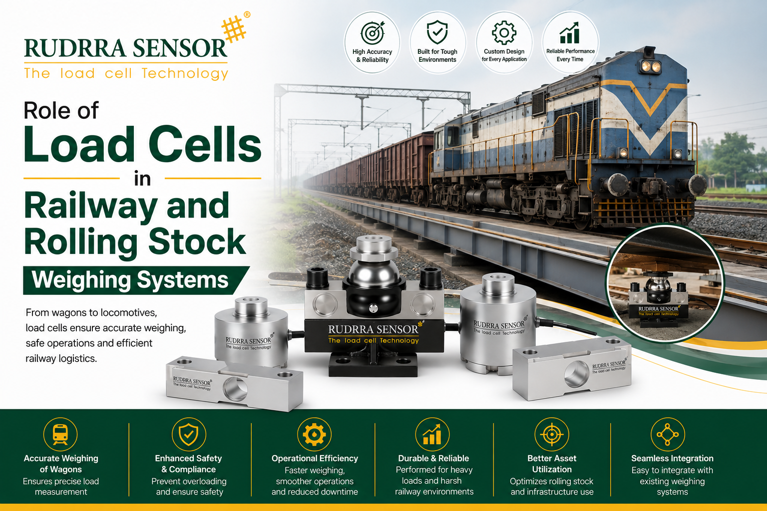
Introduction
Railways move more freight and more passengers per unit of energy than almost any other land transport mode, and that efficiency depends on a discipline that rarely gets public attention: precise, reliable weight measurement. Every wagon loaded at a freight terminal, every axle rolling over a weighbridge, every bogie assembled at a rolling stock manufacturing plant, and every locomotive coupled into a long-haul consist is subject to weight limits that exist for one overriding reason — track and rolling stock safety. Exceed those limits, even by a margin that looks small on paper, and the consequences range from accelerated rail and wheel wear to, in the worst cases, derailment.
Load cells are the measurement technology that makes railway weight compliance possible, whether that means a static weighbridge at a freight yard, an in-motion weighing system built into the track itself, or load cells integrated directly into a wagon’s bogie or suspension assembly for continuous onboard monitoring. Unlike a factory floor platform scale, railway weighing has to survive a genuinely brutal combination of conditions: constant vibration and shock loading from wheel-rail contact, wide outdoor temperature swings, exposure to rain, snow, dust, and de-icing chemicals, and — for in-motion systems — the challenge of capturing an accurate weight reading from a wagon rolling past at speed rather than sitting still.
This blog is a deep, practical look at how load cells are used across the railway and rolling stock sector: from freight wagon weighbridges and in-motion weighing systems, to axle load monitoring, to bogie and suspension-integrated load cells used by rolling stock manufacturers during design validation and production testing. We will cover the technical trust factors that separate a genuinely rail-rated load cell from a repurposed industrial sensor, walk through real-world case studies, and highlight the standards and safety numbers that matter most in this sector — including axle load limits, gross trailing load considerations, and the role of bodies such as India’s Research Designs and Standards Organisation (RDSO) and international rail weighing codes.
At Rudrra Sensor, we’ve supported freight terminal operators, rolling stock manufacturers, and railway infrastructure contractors with load cells engineered specifically for the demands of rail environments. This article draws on those application patterns to give engineers, procurement teams, and railway operations staff a genuinely useful reference — not a generic sensor overview, but a look at what actually matters when weight measurement sits this close to safety-critical rail operations.
Railway weighing is, in many respects, one of the most demanding application environments in the entire load cell industry — not because the underlying physics of force measurement is any different from other sectors, but because the operating environment combines several difficult conditions simultaneously that most other industries only encounter individually. A crane load pin faces shock loading; a chemical plant sensor faces corrosive exposure; a high-speed production line sensor faces dynamic response challenges. Railway weighing infrastructure, particularly track-side and in-motion systems, must handle shock loading, corrosive exposure, dynamic response challenges, extreme outdoor temperature swings, and electromagnetic interference all at once, over a service life measured in years of continuous, unattended operation. Understanding why each of these factors matters, and how they interact, is the foundation for specifying a railway weighing system that will actually perform reliably rather than becoming a recurring maintenance and accuracy headache.
Why Weight Measurement Matters So Much in Railway Operations
Axle load limits protect track infrastructure
Every railway track is designed and maintained to tolerate a maximum axle load — the weight transmitted through a single axle to the rail — beyond which accelerated rail wear, ballast degradation, and structural fatigue in bridges and culverts becomes a serious concern. Depending on the track classification and the railway network, permissible axle loads commonly range from around 20 to 25 tonnes on many broad-gauge freight lines, with some heavy-haul corridors engineered for axle loads exceeding 30 tonnes under specific track upgrades. Exceeding the designed axle load, even intermittently, accelerates the rate of rail fatigue cracking and can shorten the maintenance cycle of track infrastructure significantly, translating directly into higher network maintenance cost.
Overloading is a direct safety risk, not just a maintenance cost
Beyond gradual wear, an overloaded wagon changes the dynamic behavior of the vehicle on the track — its center of gravity, its suspension response to track irregularities, and its braking characteristics. Overloading is consistently identified as a contributing factor in a meaningful share of freight-related derailment investigations worldwide, which is precisely why axle load compliance is treated as a safety-critical measurement, not merely a commercial billing concern the way weight might be treated in, say, a warehouse logistics operation.
Even weight distribution matters as much as total weight
It is not enough for a wagon’s total weight to fall within its permitted gross limit — the load must also be distributed so that no individual axle or bogie exceeds its own permitted load, and so that the wagon remains within acceptable limits for lateral weight imbalance between the two rails. A wagon loaded unevenly from side to side, even while technically within its total gross weight limit, can produce excessive wheel-rail forces on one rail, contributing to irregular wear and, in severe cases, derailment risk on curves. This is why modern railway weighing systems increasingly measure weight at each individual wheel or axle position rather than only providing a single total weight figure.
Commercial billing accuracy
Freight railways typically charge customers based on the weight of goods transported, making weighing accuracy also a direct commercial and legal-for-trade concern, similar in principle to road freight weighbridges but operating under rail-specific certification frameworks. Disputes over billed weight, whether under-declared by shippers or inaccurately measured by the railway’s own weighing infrastructure, can have significant financial consequences across a network handling large freight volumes.
Wear monitoring and predictive maintenance
Beyond compliance, continuous or periodic weight and load distribution data feeds into broader rolling stock maintenance programs — helping operators identify wagons or bogies that are consistently running with abnormal weight distribution (which may indicate a suspension fault, an uneven loading practice, or a structural issue with the wagon itself) before that abnormality progresses into a more serious mechanical failure.
The scale of freight rail traffic makes small percentage errors significant
Freight railways move enormous cumulative tonnage over the life of a network — a single busy freight corridor can carry many millions of tonnes of cargo per year across thousands of individual wagon movements. At that scale, even a small systematic weighing error, whether from poorly calibrated equipment or an unaddressed axle-level overloading pattern, compounds into a meaningful cumulative effect on track wear, commercial billing accuracy, and safety margin erosion across the network. This is a key reason why railway operators increasingly treat weighing infrastructure investment as core safety and asset-protection infrastructure, rather than a secondary operational convenience.
International perspective on axle load standards
Axle load limits and the broader regulatory approach to weight compliance vary meaningfully between railway networks internationally, shaped by differences in track construction standards, historical infrastructure investment, and the mix of freight versus passenger traffic a given network carries. Heavy-haul networks specifically designed and upgraded for bulk commodities such as coal, iron ore, or grain — common in dedicated freight corridors in various parts of the world — are often engineered for meaningfully higher axle loads than general mixed-traffic networks, reflecting a deliberate trade-off between infrastructure investment and the operational efficiency of running heavier, more cost-effective freight consists. Regardless of the specific limit that applies to a given network, the underlying principle remains constant: the permitted axle load reflects a carefully engineered balance between track design life and freight capacity, and weighing infrastructure exists specifically to enforce that balance in day-to-day operation.
Where Load Cells Are Used Across the Railway and Rolling Stock Sector
Static (weighbridge-style) railway weighing systems
The most traditional application is a dedicated rail weighbridge — a section of track built over a load-cell-supported weighing platform, where a wagon or locomotive is stopped and weighed statically, either as a single unit or coupled as part of a train that is weighed axle by axle or wagon by wagon as it is moved slowly across the weighing section. Static systems generally achieve the highest accuracy of any railway weighing method, since the vehicle is stationary and vibration/dynamic effects are eliminated from the measurement, making them the preferred choice where legal-for-trade billing accuracy is the primary requirement.
In-motion weighing (weigh-in-motion) systems
In-motion railway weighing systems measure wagons as they pass over the weighing section at normal or near-normal operating speed, without requiring the train to stop or slow significantly. This dramatically improves throughput at busy freight yards and junctions compared to static weighing, but requires load cells and associated signal processing engineered specifically to extract an accurate weight reading from a dynamic, vibration-heavy signal — a meaningfully more demanding measurement problem than static weighing, and one where the quality of the load cell’s dynamic response characteristics directly determines system accuracy.
Axle load and wheel load monitoring
Some railway weighing installations are specifically designed to measure individual axle loads or even individual wheel loads (left and right rail separately), rather than only total wagon weight. This finer-grained measurement is particularly valuable for detecting uneven load distribution, verifying compliance with axle load limits on specific track sections, and supporting investigations into wheel-rail interaction issues such as excessive lateral force or wheel unloading on curves.
Bogie and suspension-integrated load cells for rolling stock manufacturing
Rolling stock manufacturers and testing laboratories use load cells integrated directly into bogie test rigs and suspension assemblies during vehicle design validation, structural testing, and production quality control — measuring static and dynamic load transfer through the bogie’s springs, dampers, and structural members under simulated operating conditions before a new wagon or coach design enters service.
Locomotive and coupler force measurement
Load cells are also used to measure coupler forces between locomotives and wagons, particularly relevant for long, heavy freight consists where excessive coupler forces during acceleration, braking, or negotiating grades can risk coupler failure or contribute to “train action” dynamics that increase derailment risk on long trains. Specialized load cells integrated into coupler assemblies or draw gear provide this data both for operational monitoring and for engineering studies on train handling practices.
Container and intermodal terminal weighing
At intermodal freight terminals, load cells integrated into container handling equipment (reach stackers, gantry cranes, rail-mounted gantries) weigh containers as they are loaded onto or removed from rail wagons, feeding both terminal operational systems and — in many jurisdictions — regulatory verified gross mass (VGM) compliance requirements that apply to containerized freight.
Track-side structural and bridge load monitoring
Beyond vehicle weighing, load cells are also used in railway civil engineering applications — monitoring load transfer through bridge bearings, structural health monitoring on major rail bridges, and load verification during the installation or replacement of heavy track structural components — an application area that overlaps with general heavy infrastructure load monitoring but is included here because it frequently shares project scope and procurement with rolling stock weighing systems on major rail infrastructure programs.
Wheel impact load detection systems
A closely related application, distinct from routine weight compliance but sharing similar sensor technology, is wheel impact load detection — track-side instrumentation designed to detect wheels with flats, out-of-round profiles, or other defects that generate abnormally high, sharp impact forces as they roll over the track. While these systems are sometimes built around dedicated strain gauge arrays bonded to the rail itself rather than discrete load cells, the underlying measurement principle and many of the environmental and dynamic response engineering challenges are directly shared with railway weigh-in-motion systems, and operators frequently procure both capabilities as part of the same track-side instrumentation program given the overlapping infrastructure and signal processing requirements.
Rolling stock manufacturing quality control
Beyond the design validation testing described later in this article, load cells are also used in day-to-day production quality control at rolling stock manufacturing facilities — verifying that assembled bogies, suspension units, and structural subassemblies meet specified load-bearing performance before leaving the factory, providing a documented quality record for each production unit rather than relying solely on design-stage validation to guarantee consistent manufacturing quality across an entire production run.
How Railway Load Cells Differ From Standard Industrial Load Cells
Shock and vibration resistance
Wheel-rail contact generates continuous vibration and, at rail joints, welds, or track irregularities, sharp shock loading events that transmit directly into any load cell positioned in or near the track structure or vehicle undercarriage. Railway-rated load cells are engineered with mechanical designs and fatigue ratings specifically suited to withstand millions of these shock and vibration cycles over the sensor’s service life, considerably more demanding than the vibration environment most industrial weighing applications experience.
Wide outdoor temperature and weather exposure
Track-side and undercarriage-mounted load cells operate fully exposed to whatever climate the railway network passes through — from sub-zero winter conditions in temperate and high-altitude regions to intense summer heat on steel rail and ballast that can reach temperatures well above ambient air temperature. Railway load cells are typically specified with wide temperature compensation ranges and housings that resist thermal cycling fatigue over years of continuous outdoor service.
Contamination resistance
Ballast dust, brake dust, de-icing salt, oil and grease from rolling stock, and general environmental grime all accumulate on track-side and undercarriage equipment. Railway load cells require robust sealing — commonly IP67 or IP68 — along with corrosion-resistant materials, since the combination of moisture and de-icing chemicals is particularly aggressive toward standard mild steel components.
High-speed dynamic response for in-motion systems
As discussed above, weigh-in-motion systems place unusual demands on a load cell’s dynamic response characteristics, since the sensor must accurately capture the weight signature of a wheel or axle passing over the sensing element in a fraction of a second, filtering out vibration noise while still responding fast enough to capture the true peak and average load values needed for an accurate weight calculation.
Mechanical integration with rail and rolling stock structures
Track-embedded load cells must integrate with the rail and sleeper/track-bed structure without compromising track geometry or structural integrity — a specialized mechanical engineering challenge distinct from a typical industrial platform scale foundation. Similarly, bogie or suspension-integrated load cells must fit within tightly constrained undercarriage space envelopes while surviving the harsh vibration and contamination environment described above.
Electromagnetic interference considerations
Railway environments, particularly electrified lines, involve significant electromagnetic interference from traction power systems, signaling equipment, and overhead or third-rail electrification. Load cell wiring, shielding, and signal conditioning in railway applications must be specifically designed to reject this interference, since a standard industrial cabling approach that works fine in a typical factory environment can pick up significant noise near railway traction infrastructure.
A Practical Specification Checklist
Before requesting a quotation for a railway weighing load cell system, it helps to work through a structured checklist, since railway weighing projects typically involve both electrical/instrumentation engineering and civil/mechanical integration considerations that need to be resolved together:
- Weighing method required — static weighbridge, in-motion (weigh-in-motion), individual axle/wheel load monitoring, or onboard bogie-integrated measurement.
- Line speed for in-motion systems — including the full range of speeds the system needs to accurately weigh across, since accuracy typically varies with speed band.
- Axle/wagon capacity range — matched to the actual rolling stock types using the line, including the heaviest loaded freight wagons expected.
- Required accuracy class — driven by whether the primary purpose is legal-for-trade billing, safety compliance verification, or general operational monitoring.
- Environmental exposure at the installation site — temperature range, exposure to de-icing chemicals, flooding risk, and whether the line is electrified (affecting EMI shielding requirements).
- Individual axle/wheel resolution requirement — whether total wagon weight is sufficient or individual axle/wheel load data is needed for compliance or maintenance purposes.
- Integration requirements — how weighing data needs to feed into terminal operating systems, signaling systems, or maintenance management software.
- Applicable regulatory framework — relevant national railway weighing standards and certification requirements (such as RDSO specifications in India, or equivalent frameworks in other rail networks).
- Civil/track integration constraints — available space, track geometry restrictions, and coordination requirements with track maintenance schedules for installation.
- Calibration and long-term verification plan — how the installed system will be periodically verified against reference standards throughout its service life.
Trust Factors: Technical Benchmarks for Railway Load Cells
| Trust Factor | Why It Matters | Typical Benchmark |
| Shock/impact rating | Withstands rail joint and wheel-flat impact events | Rated for repeated shock loading well above nominal working load |
| Fatigue life | Ensures service life under millions of wheel-pass cycles | Multi-million cycle fatigue rating at rated dynamic load |
| IP rating | Protects against ballast dust, moisture, de-icing chemicals | IP67 minimum for track-side; IP68 for submersion-prone locations |
| Temperature range | Withstands full outdoor climate exposure | Typically -25°C to +70°C or wider for track-side installations |
| Accuracy class | Matches application purpose (billing vs monitoring) | Legal-for-trade classes for billing; relaxed classes acceptable for pure monitoring |
| Dynamic response | Enables accurate weigh-in-motion measurement | Response characteristics matched to maximum line speed for the system |
| EMI/EMC resistance | Prevents interference from traction and signaling systems | Shielded cabling and signal conditioning rated for electrified line environments |
| Corrosion resistance | Withstands de-icing salt and general environmental exposure | Stainless steel or equivalent corrosion-resistant housing |
| Calibration traceability | Confirms measurement accuracy is verifiable | Certificate traceable to a recognized national/international accreditation body |
| Regulatory compliance | Confirms suitability for the specific railway network | Compliance with relevant national railway weighing/instrumentation standards |
Why fatigue life is the defining engineering challenge
A single freight wagon axle can pass over a fixed track-side weighing point many times over the life of an active freight corridor, and a busy junction or terminal can see thousands of axle passes per day across all the wagons using that section of track. This means a track-side load cell’s fatigue life — its ability to survive millions of loading cycles without developing microcracks or drift in its sensing element — is arguably the single most important design parameter, more so than raw accuracy specification, because a sensor that is highly accurate when new but fatigues prematurely under this cycle count becomes a maintenance liability and a measurement risk within a relatively short operational period if not properly engineered for the duty cycle.
Why dynamic response accuracy is central to in-motion systems
Static weighing, by definition, gives the load cell time to settle to a stable reading. In-motion weighing does not have that luxury — the entire weight measurement for a given axle must be captured and processed within the brief window that axle is in contact with or near the sensing element, at whatever speed the train is moving. A load cell with response characteristics not properly matched to the target line speed range will either miss the true peak load or introduce measurement noise that degrades overall system accuracy, which is why weigh-in-motion system accuracy specifications are typically expressed as a function of speed range, not as a single blanket accuracy figure the way a static system’s accuracy might be described.
Relevant regulatory and standards frameworks
Railway weighing systems, particularly those used for commercial billing or safety compliance, typically need to meet specific regulatory frameworks:
- RDSO (Research Designs and Standards Organisation) specifications govern various aspects of railway rolling stock, track, and instrumentation standards for Indian Railways, and are a key reference point for load cell systems supplied into Indian rail freight and infrastructure projects.
- National weights and measures authorities in most countries govern legal-for-trade requirements for any weighing system used for commercial billing purposes, similar in principle to road weighbridge certification but with rail-specific considerations.
- International rail standards bodies, including frameworks referenced by organizations such as the International Union of Railways (UIC), provide broader technical reference points for rolling stock and infrastructure design that rail weighing system suppliers often need to be conversant with, particularly for cross-border or export projects.
- General industrial load cell standards, such as OIML R60 metrological accuracy classifications, remain relevant as a technical reference for the underlying sensor accuracy classification, even though the full system certification for rail applications typically involves additional rail-specific requirements beyond the base sensor standard.
A supplier who can speak specifically to which of these frameworks applies to your particular network and application — rather than offering a generic “certified” assurance — is a stronger indicator of genuine railway sector experience.
Case Study 1: Reducing Overload-Related Track Damage at a Freight Terminal
The situation: A bulk freight operator running a dedicated line from a mining loading facility to a port terminal was experiencing accelerated rail wear and an increasing frequency of track maintenance interventions on a specific section of line, well ahead of the expected maintenance cycle for that track class.
The challenge: Investigation by the track engineering team found that a meaningful proportion of wagons departing the loading facility were running above their designed axle load limit, a pattern that had gone undetected because the facility’s existing weighing process only verified total train weight against the locomotive’s haulage capacity, without checking individual wagon or axle-level compliance against the track’s designed axle load limit.
The solution: A static weighbridge system with individual axle load measurement capability was installed at the loading facility’s exit road, using railway-rated load cells sealed to IP67 and specified with a fatigue rating suited to the facility’s continuous, high-frequency loading cycle. The system was integrated with the facility’s loading control system so that any wagon exceeding its permitted axle load triggered an alert before the train was dispatched, allowing loading adjustments to be made prior to departure rather than discovering the issue after the fact.
The outcome: Within the first year of operation, the operator reported a significant reduction in axle-load-related track maintenance interventions on the affected line section, along with measurable extension of the interval between scheduled track maintenance cycles. The axle-level loading data also became a standing input into the facility’s loading procedures, used to train loading operators on correct material distribution across wagons rather than relying solely on total train weight as the loading benchmark.
Lessons for similar projects: This case illustrates a distinction that is easy to overlook: total train weight compliance does not guarantee individual axle load compliance, and the two require different measurement approaches. Facilities that only verify aggregate weight against locomotive haulage capacity may be missing exactly the kind of localized overloading that causes concentrated track damage, even while overall tonnage figures look entirely normal. It’s also worth noting how the operator closed the loop: rather than treating the weighbridge as a passive compliance check, they integrated the axle-level data directly into loading procedures and operator training, turning a measurement system into an active process improvement tool rather than a simple pass/fail gate.
Case Study 2: Weigh-in-Motion System for a High-Throughput Junction
The situation: A railway network operator needed to verify wagon weight compliance at a busy freight junction handling a high volume of daily wagon movements, without introducing the delay that a static weighing stop would add to an already congested section of the network.
The challenge: The junction’s existing weighing arrangement relied on periodic manual spot-checks at a distant static weighbridge, meaning the vast majority of wagon movements through the junction were never actually weighed, and any non-compliant wagons could pass through undetected for extended periods between spot-checks.
The solution: A weigh-in-motion system was installed directly into the track structure at the junction, using load cells specifically engineered for dynamic response across the junction’s typical operating speed range, with shock and fatigue ratings suited to the high daily axle-pass volume the location would experience. The system was configured to capture individual axle and total wagon weight for every train passing through the junction at normal operating speed, feeding data automatically into the network’s central monitoring system without requiring any change to normal train movements.
The outcome: The system began capturing weight data on effectively all wagon movements through the junction rather than the small sample previously covered by periodic manual spot-checks, and within the first several months of operation identified a small but consistent number of non-compliant wagons per week that would previously have gone entirely undetected. The operator was also able to use the comprehensive weight dataset to build a much more accurate picture of actual traffic loading patterns through the junction for broader network capacity planning purposes.
Lessons for similar projects: This case highlights the fundamental limitation of spot-check-based compliance verification: however well-intentioned, periodic manual weighing only samples a small fraction of actual traffic, leaving the majority of movements unverified. A properly engineered weigh-in-motion system, despite requiring greater upfront investment and more demanding sensor specification than a static weighbridge, delivers comprehensive rather than sampled compliance data — a meaningfully different and more robust safety and compliance posture for high-traffic locations. It’s also worth noting that the value of this system extended well beyond its original compliance purpose, since the comprehensive traffic loading dataset it generated became a genuinely useful planning input — a reminder that investment in high-quality measurement infrastructure often pays dividends in applications beyond the one that originally justified the purchase.
Case Study 3: Bogie Load Testing for a New Freight Wagon Design
The situation: A rolling stock manufacturer developing a new high-capacity freight wagon design needed to validate the structural performance of the wagon’s bogie and suspension assembly under simulated operating loads before submitting the design for regulatory approval and entering production.
The challenge: The manufacturer’s existing test rig used general-purpose industrial load cells not originally specified for the combination of high static load, dynamic cyclic loading, and precise multi-point measurement (verifying load transfer through each spring and damper location independently) required for a thorough bogie validation program, leading to inconsistent test data that made it difficult to confidently characterize the design’s structural margins.
The solution: The test rig was upgraded with load cells specifically selected for high-cycle fatigue testing applications, rated for the precise combination of static and dynamic load ranges the bogie validation program required, with multi-point instrumentation allowing simultaneous, independent measurement at each spring and damper location rather than only a single aggregate load figure. Calibration was performed with full traceability appropriate for the regulatory submission documentation the design approval process required.
The outcome: The improved instrumentation allowed the manufacturer to complete the bogie validation program with significantly more consistent, statistically reliable test data, supporting a more confident and better-documented regulatory submission. The multi-point load data also revealed a minor asymmetry in load distribution across the bogie’s suspension elements under certain simulated loading conditions — a finding that led to a small design refinement before production tooling was finalized, avoiding a potential in-service issue that might otherwise only have been discovered after wagons had already entered revenue service.
Lessons for similar projects: This case demonstrates the value of properly specified, multi-point load measurement in engineering validation contexts, not just operational weighing contexts. A single aggregate load reading can mask exactly the kind of localized imbalance that matters most for structural design validation — reinforcing a theme that recurs throughout railway weighing applications: understanding load distribution, not just total load, is very often where the real engineering insight lies.
Case Study 4: Coupler Force Monitoring on a Long, Heavy Haul Freight Consist
The situation: A heavy-haul freight operator running unusually long, heavy trains on a corridor with significant grade changes was investigating a pattern of coupler-related mechanical incidents, including several occurrences of coupler damage and, on one occasion, a coupler separation event that fortunately did not result in a derailment but caused a significant operational disruption and safety review.
The challenge: Train handling practices — throttle and braking sequencing across a very long consist — directly affect the in-train forces experienced at each coupler position, and on long, heavy trains operating over varied grade profiles, these forces can vary substantially and unpredictably along the length of the train depending on exactly how the locomotive crew manages acceleration, braking, and any mid-train or rear distributed power units. Without direct force measurement, the operator’s engineering team had only indirect indicators (train handling logs, incident reports) to work from when investigating the pattern of coupler issues.
The solution: Load cells were integrated into coupler/draw gear assemblies at multiple points along a representative set of test trains, providing direct, continuous coupler force measurement throughout representative revenue trips across the affected corridor. The load cells were specified for the significant dynamic force range and shock loading associated with coupler forces during braking and acceleration events, with data logged and correlated against train handling records (throttle, brake application, train position on the grade profile) for detailed engineering analysis.
The outcome: The resulting data allowed the operator’s engineering team to identify specific combinations of train handling technique and grade position that produced excessive coupler forces, well above what had been assumed from theoretical train dynamics modeling alone. This directly informed revised train handling guidance for locomotive crews operating on the affected corridor, along with engineering review of distributed power unit placement on the heaviest consists. Coupler-related incidents on the corridor decreased significantly in the period following the guidance changes.
Lessons for similar projects: This case illustrates how direct force measurement can validate or correct assumptions built into theoretical modeling — train dynamics simulations are a valuable engineering tool, but they rely on assumptions about friction, coupler slack, and crew behavior that can diverge from actual operating conditions in ways that are difficult to predict without real measurement data. For any operator managing long, heavy consists over challenging grade profiles, direct coupler force instrumentation, even on a temporary or representative-sample basis rather than permanent fleet-wide installation, can surface exactly the kind of operationally specific insight that generic engineering assumptions may miss.
Common Installation and Specification Mistakes to Avoid
Railway weighing systems sit at the intersection of instrumentation engineering, civil/track engineering, and regulatory compliance, which means specification and installation mistakes in this sector often trace back to a gap between these disciplines rather than a straightforward sensor selection error. The following are the issues we see most frequently across static, in-motion, and rolling-stock-integrated railway weighing projects.
Verifying only total weight, not axle-level or wheel-level compliance
As Case Study 1 demonstrated, aggregate weight compliance does not guarantee individual axle or wheel-level compliance. Any application where track damage, wheel-rail force limits, or axle load regulations are a concern should specify measurement resolution down to the individual axle or wheel level, not just total wagon or train weight.
Underestimating fatigue life requirements for high-traffic locations
A load cell that appears adequately rated for a modest daily traffic volume may be significantly under-specified for a busy junction or terminal seeing very high daily axle-pass counts. Fatigue life should always be calculated against the actual, realistic traffic volume expected at the specific installation location over its intended service life, not a generic assumption.
Mismatching dynamic response specification to actual line speed range
Specifying a weigh-in-motion system’s load cells for a single “typical” speed without accounting for the full range of speeds trains might realistically pass through the location — including any variation from scheduling, congestion, or seasonal speed restrictions — can produce inconsistent accuracy across different operating conditions.
Inadequate EMI shielding near electrified track
As discussed earlier, electrified railway lines introduce significant electromagnetic interference that standard industrial cabling practices may not adequately address. Underestimating shielding requirements near traction power infrastructure is a common source of noisy, unreliable signals that are often misdiagnosed as sensor faults rather than an EMI/cabling issue.
Insufficient environmental sealing for track-side locations
Track-side installations face an unusually harsh combination of moisture, ballast dust, and de-icing chemical exposure. Specifying a load cell with an environmental rating suited only to a sheltered or indoor industrial environment, rather than the genuine outdoor track-side exposure the sensor will actually face, leads to premature failure well short of the expected service life.
Overlooking civil/track integration constraints during specification
Railway weighing installations, particularly track-embedded systems, must integrate with existing track geometry, ballast structure, and maintenance access requirements. Specifying a sensor and mounting design without close coordination with track engineering and maintenance teams can lead to installation difficulties or ongoing maintenance access conflicts that could have been avoided with earlier coordination.
Skipping traceable calibration for compliance-critical systems
For any railway weighing system tied to commercial billing or regulatory axle load compliance, a load cell without traceable, documented calibration undermines the legal and safety defensibility of the system’s measurements — a particularly important consideration given how directly railway weighing data can be tied to safety investigations or commercial disputes.
Failing to plan for periodic verification and maintenance access
Given the harsh operating environment and safety-critical nature of railway weighing, a maintenance and periodic calibration verification plan should be established at the design stage, including physical access provisions for maintenance personnel — an easy detail to overlook when a system is designed primarily around initial installation rather than its full multi-year service life.
A cross-disciplinary problem requiring cross-disciplinary planning
Looking across this list, the recurring theme is that railway weighing failures are rarely caused by a fundamentally flawed sensor choice in isolation — they are far more often caused by a gap between instrumentation specification and the civil, mechanical, or regulatory context the system actually operates in. The most successful railway weighing installations we’ve been involved with are the ones where instrumentation engineers, track/civil engineers, and compliance or regulatory specialists were involved together from the early design stage, rather than instrumentation being treated as a bolt-on addition to an already-finalized civil design. Given how much is riding on accurate railway weighing data — quite literally, in terms of the tonnage passing over the track — that level of early cross-disciplinary coordination is a worthwhile investment relative to the cost of correcting a poorly integrated system after installation.
Cost vs. Value: Justifying Investment in Railway-Grade Load Cells
Railway-grade load cells, engineered for the shock, vibration, environmental, and fatigue demands described throughout this article, cost meaningfully more than general industrial load cells repurposed for a rail application. The value case for the investment is strong when the full picture is considered:
- Track maintenance cost avoidance: As Case Study 1 demonstrated, undetected axle overloading accelerates track wear and shortens maintenance cycles, a cost that compounds across an entire network far beyond the price of the weighing equipment itself.
- Safety risk reduction: Given the established link between overloading and derailment risk, properly specified weighing infrastructure represents a direct safety investment, not merely an operational convenience.
- Reduced compliance and billing disputes: Accurate, traceable weighing data reduces the frequency and cost of disputes with freight customers over billed weight, and strengthens the railway’s position in any regulatory compliance review.
- Comprehensive rather than sampled compliance data: As Case Study 2 demonstrated, weigh-in-motion systems that capture data on effectively all traffic, rather than periodic manual samples, provide a fundamentally more robust compliance and safety posture.
- Design validation confidence: As Case Study 3 demonstrated, properly instrumented test and validation programs reduce the risk of costly in-service design issues being discovered only after rolling stock has entered revenue service.
- Operational safety insight beyond simple compliance: As Case Study 4 demonstrated, direct force measurement can reveal operational risk factors — such as excessive coupler forces under specific train handling conditions — that theoretical modeling alone may not fully capture, informing safer operating practices.
- Extended service life reduces long-term cost: A correctly fatigue-rated, properly sealed railway load cell will typically outlast an under-specified industrial substitute by a considerable margin, spreading the higher initial investment over many more years of reliable service.
Framing this as a total cost of ownership and safety-risk decision, rather than a simple unit price comparison, is the right lens for railway infrastructure and rolling stock procurement teams evaluating weighing system investments.
Choosing the Right Supplier for Railway Weighing Load Cells
Given the specialized combination of mechanical, environmental, and regulatory requirements involved, supplier selection matters significantly for railway weighing projects:
- Demonstrated experience in railway or heavy transport applications, since the failure modes and design considerations differ meaningfully from general industrial weighing
- Ability to support both static and dynamic (weigh-in-motion) system requirements, given how different the underlying sensor specification needs are between these two approaches
- Familiarity with relevant regulatory frameworks for your specific network, including national railway instrumentation standards and legal-for-trade requirements where applicable
- Documented fatigue and environmental testing behind their railway-rated product line, not simply a relabeled industrial load cell
- Calibration traceability and documentation support suited to regulatory submission and audit requirements
- Willingness to engage in joint civil/mechanical integration planning, given how closely railway weighing system performance depends on correct track or vehicle structural integration, not just sensor selection alone
At Rudrra Sensor, we work with railway infrastructure teams and rolling stock manufacturers to understand the specific traffic patterns, environmental exposure, and regulatory context of each project before recommending a load cell configuration — because, as the case studies above illustrate, railway weighing performance depends as much on correct application engineering as it does on the sensor’s own specifications. This typically means an early conversation covering not just the target capacity and accuracy class, but the realistic daily traffic volume the installation will see, the specific environmental conditions at the exact installation site (which can vary meaningfully even within a single network depending on climate zone, electrification status, and proximity to coastal or industrial areas), and the regulatory documentation the finished system will need to support — all details that shape the final sensor specification well beyond a simple capacity number.
Emerging Trends in Railway Weighing Technology
Wider adoption of continuous weigh-in-motion monitoring
As demonstrated in Case Study 2, the shift from periodic spot-check weighing to comprehensive weigh-in-motion coverage is a broader industry trend, driven by both safety considerations and the operational efficiency benefit of not requiring trains to stop for weighing.
Integration with predictive maintenance and asset management systems
Railway networks are increasingly integrating weighing data into broader asset management platforms, correlating axle load patterns with track maintenance records and rolling stock maintenance history to identify emerging issues — whether in specific track sections experiencing disproportionate loading or specific wagons showing abnormal load distribution patterns over time.
Onboard, continuous load monitoring on rolling stock
Rather than relying solely on track-side weighing infrastructure, some rolling stock operators are exploring onboard load cells integrated into wagon suspension systems that provide continuous load and load distribution data throughout a journey, rather than only at discrete weighing points — a capability that could eventually support real-time load-based train handling adjustments and more granular maintenance condition monitoring.
Digital and networked railway weighing infrastructure
As with other load cell application areas covered elsewhere, railway weighing systems are increasingly moving toward digital, networked sensor architectures that simplify data aggregation across multiple weighing points on a network and support more sophisticated analytics than legacy point-to-point analog systems allowed.
Greater emphasis on individual wheel load and lateral force measurement
Beyond simple weight measurement, there is growing interest in more sophisticated instrumented wheelset and track-side systems capable of measuring individual wheel loads and lateral wheel-rail forces, supporting more detailed vehicle-track interaction studies relevant to both safety research and next-generation rolling stock design.
Data-driven train handling and operational optimization
As illustrated in Case Study 4, the availability of direct force measurement data — whether from coupler instrumentation, bogie load monitoring, or weigh-in-motion systems — is increasingly feeding into broader operational optimization efforts, from train handling guidance to consist planning, moving railway weighing data from a purely compliance-focused function toward a genuine operational intelligence resource.
Frequently Asked Questions (FAQs)
Q1: What’s the difference between static weighbridge and weigh-in-motion railway weighing systems?
Static systems require the train or wagon to stop (or move very slowly) across the weighing platform, generally achieving the highest accuracy since dynamic effects are minimized, and are well suited to legal-for-trade billing applications. Weigh-in-motion systems weigh wagons at normal operating speed without requiring a stop, improving throughput at busy locations but requiring load cells and signal processing specifically engineered for accurate dynamic measurement.
Q2: Why is axle-level weight measurement important if total wagon weight is already being checked?
Total weight compliance does not guarantee that an individual axle isn’t overloaded relative to the track’s designed axle load limit, since load can be unevenly distributed within a wagon even while the aggregate figure looks acceptable. Axle-level measurement catches this kind of localized overloading that aggregate weighing alone would miss.
Q3: How often should railway load cells be recalibrated or verified?
This depends on the specific application, traffic volume, and regulatory requirements applicable to your network, but given the safety and compliance stakes involved, periodic verification against a traceable reference standard — on a schedule agreed with your calibration and regulatory framework — is standard practice for compliance-critical railway weighing systems.
Q4: Can existing industrial load cells be used for railway weighing applications?
Generally not recommended for track-side or vehicle-integrated applications, since standard industrial load cells are rarely rated for the combination of shock, vibration, fatigue, and environmental exposure that railway applications involve. Using an under-specified sensor risks premature failure and, in compliance-critical applications, undermines the reliability of the weighing data itself.
Q5: Do coupler force and bogie load monitoring systems need to be permanently installed, or can they be used on a temporary basis?
Both approaches are used in practice. Permanent installation supports continuous operational monitoring and long-term trend analysis, while temporary, representative-sample instrumentation — as in Case Study 4 — is often sufficient for a focused engineering investigation, and can be a more cost-effective way to gather the specific data needed to answer a particular operational or design question before committing to permanent fleet-wide instrumentation.
Conclusion
Railway and rolling stock weighing sits at an unusually demanding intersection of safety-critical measurement and genuinely harsh operating conditions — constant vibration, wide environmental exposure, high-cycle fatigue demands, and, for in-motion systems, the added challenge of capturing an accurate reading from a wagon that never stops moving. The four case studies above — a freight terminal catching axle-level overloading that aggregate weighing had missed, a junction moving from sampled to comprehensive weigh-in-motion coverage, a rolling stock manufacturer using properly instrumented bogie testing to catch a design issue before production, and a heavy-haul operator using coupler force data to correct risky train handling practices — all point to the same underlying theme: railway weighing and force measurement done properly reveals problems that a less rigorous approach would simply miss, often with real safety, maintenance cost, or design-quality consequences.
If your organization is specifying weighing infrastructure for a railway network, a freight terminal, or a rolling stock manufacturing program, the questions worth asking are consistent with the broader theme of this article: does the system measure at the resolution actually needed (axle or wheel level, not just aggregate weight)? Is the sensor genuinely rated for the fatigue, shock, and environmental demands of your specific installation, not just a relabeled industrial product? And can your supplier back up their design with documented, traceable calibration and genuine railway sector application experience?
At Rudrra Sensor, we work through exactly these questions with every railway and rolling stock weighing project, because in this sector, a load cell is never just a sensor — it’s a direct input into track safety, rolling stock design integrity, and network compliance.
Need a load cell solution engineered for your railway or rolling stock weighing application? Get in touch with the Rudrra Sensor engineering team to discuss your traffic volume, environmental conditions, and regulatory requirements, and we’ll help you specify a system built for the real operating demands of your network.