


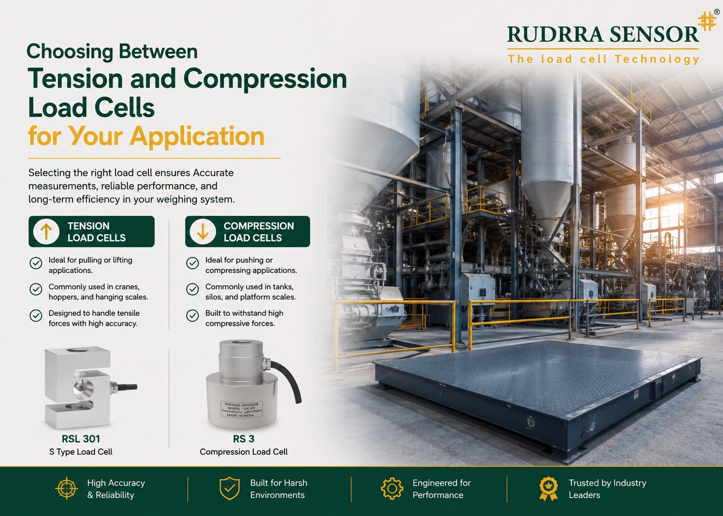
Of all the decisions an engineer makes when specifying a load cell, none is more fundamental — and surprisingly, none is more often gotten wrong — than the choice between a tension load cell and a compression load cell. This is not a minor technical detail to be resolved after the more important decisions have been made; it is, in fact, one of the very first questions that should be asked, because it determines the entire mechanical architecture of the weighing or force measurement system: how the load cell is mounted, how the force is transmitted to it, what mounting hardware is required, and ultimately whether the system will deliver accurate, reliable measurement or suffer from chronic errors that no amount of recalibration can fix.
The terms themselves are simple enough on the surface. A compression load cell measures force that pushes down on it — the classic example being a platform scale, where the weight of an object presses down on the load cells beneath it. A tension load cell measures force that pulls on it — the classic example being a crane scale, where a suspended load pulls down on the load cell from below. But the apparent simplicity of this distinction conceals a genuinely important engineering decision, because many real-world applications are not as clear-cut as a platform scale or a crane scale. Vessels with internal agitators, structures subject to wind loading, machines with reversing force directions, and dozens of other scenarios require careful analysis of the actual force path before the tension-versus-compression decision can be made correctly.
Getting this decision wrong has consequences that range from inconvenient to severe. A compression load cell installed where the actual force is tensile will simply fail to register any reading — the load cell’s spring element will not deform in the way needed to generate a signal, and the system will appear completely non-functional. More insidiously, a load cell selected for the wrong primary force direction but installed in a way that happens to produce some signal may give readings that are non-linear, unstable, or subject to large errors under conditions that were not anticipated during the original specification. And in some cases — vessels that experience both tension and compression depending on operating conditions, or machinery where the force direction can reverse — neither a pure tension nor a pure compression load cell is the right answer at all; a bidirectional design is required.
This comprehensive guide is designed to remove the guesswork from this decision entirely. We begin with the fundamental engineering principles that distinguish tension and compression load cells — not just what they measure, but how their internal mechanical design differs and why that design difference matters. We then work through ten detailed real-world application scenarios, each illustrating a different category of force measurement challenge and explaining exactly how to determine the correct load cell type for that scenario. A consolidated decision framework, technical specification guidance, and answers to the most common questions engineers ask when facing this choice complete the guide.
| 2 Types
Fundamental force directions — pull or push |
S-Type
Most common bidirectional load cell design |
50%+
Of installation errors trace to wrong force-path analysis |
1 Decision
That determines your entire mounting architecture |
The Fundamental Difference
How tension and compression load cells work — and why the distinction matters at the level of mechanical design
Force Direction and Spring Element Geometry
Every strain gauge load cell operates on the same basic principle: a precisely machined metal spring element deforms elastically when force is applied, and strain gauges bonded to the spring element’s surface measure this deformation, converting it into an electrical signal. But the geometry of the spring element — and critically, the way the load cell is mechanically connected to the structure applying the force — differs fundamentally depending on whether the load cell is designed to measure tension (pulling) or compression (pushing) force.
A compression load cell’s spring element is typically a column, disc, or short cylindrical body designed to shorten very slightly when a downward (compressive) force is applied to its top surface and reacted at its base. The load cell sits beneath the load, supporting it from below. Compression load cells are mechanically simple to install in many applications — the load cell can simply be placed under a platform, vessel leg, or structure, with the weight of the supported object providing the compressive force naturally through gravity. This simplicity is one reason compression load cells are so widely used: in many applications, gravity does the work of applying the force in the correct direction without any special fixturing.
A tension load cell’s spring element is shaped differently — commonly an S-shaped beam (giving rise to the name ‘S type load cell’), a dumbbell shape, or a rod-like element — specifically designed to elongate very slightly when pulled from both ends. Critically, a tension load cell must be mechanically connected at both ends to the structure transmitting the force: one end attached to the fixed anchor point, the other end attached to the load being measured, typically through eye bolts, clevises, shackles, or threaded rod ends. This means tension load cells inherently require more deliberate fixturing than compression load cells — there is no equivalent to ‘simply placing it under the load’ for a tension measurement.
Why You Cannot Simply Substitute One for the Other
It might seem that a sufficiently clever installation could allow a compression load cell to measure tension, or vice versa — for example, by using a lever or pulley to redirect the force. While such mechanical redirections are sometimes used in specialised test rig applications, they introduce additional sources of error (friction in pulleys, backlash in levers, alignment sensitivity) and are never the correct default approach for a production weighing or force measurement system. The fundamental reason is that the spring element’s internal stress pattern under tension is different from its stress pattern under compression, even for the same nominal magnitude of force — and the strain gauge positions are optimised for one specific stress pattern.
A compression-only load cell subjected to a tensile force will, at best, produce no usable signal (because the spring element is not designed to elongate in a way that the gauges can sense correctly) and at worst will be mechanically damaged, since most compression load cell designs have no provision for being pulled apart — there is often no positive mechanical connection holding the two ends together, only the compressive contact maintained by the weight of the load. Attempting to use a compression load cell in a tension application is therefore not merely suboptimal — it frequently does not work at all.
The Most Common Specification Mistake
The single most common load cell specification error encountered in the field is selecting a load cell based on its capacity and accuracy class while overlooking the force direction entirely — often because the engineer focused on ‘how much weight’ without first asking ‘which direction is the force actually applied.’ This mistake is particularly common in retrofit and upgrade projects, where an engineer replacing an old or failed load cell defaults to whatever type was used previously without re-examining whether the original specification was even correct for the application. Always determine force direction first, before any other specification parameter.
Why This Decision Comes First
Force direction as the foundational parameter that shapes every other aspect of system design
The Cascading Consequences of the Tension/Compression Decision
Once the force direction has been correctly identified and the appropriate load cell type selected, a cascade of downstream decisions follows logically. For a compression application, the mounting hardware will typically be cup-and-ball assemblies, mounting feet, or load buttons that allow the load cell to sit beneath a structure while accommodating minor angular misalignment. For a tension application, the mounting hardware will typically be clevises, eye bolts, swivel joints, or rod end bearings that allow the load cell to hang in-line within a cable, chain, or rod assembly while accommodating the natural swing and alignment changes of a suspended load.
The structural design of the surrounding equipment is also shaped by this decision. A compression weighing system requires a rigid platform or vessel support structure beneath the load, engineered to transmit force downward into the load cells. A tension weighing system requires an overhead support structure (a crane, a gantry, an anchor point) from which the load can be suspended, with the load cell positioned in-line within the suspension path. These are fundamentally different structural engineering problems, and retrofitting one approach into infrastructure designed for the other is often impractical or prohibitively expensive.
Force Direction Analysis — A Systematic Approach
Before specifying any load cell, the engineer should work through a simple but rigorous analysis of the actual force path in the application:
- Identify the load: what physical object or material is being weighed or whose force is being measured?
- Identify how the load is supported or constrained: is it resting on a surface (suggesting compression), hanging from a support (suggesting tension), or connected via a mechanism that could apply either (requiring more detailed analysis)?
- Trace the force path from the load, through any intermediate structure, to the point where the load cell will be installed — at every point along this path, determine whether the structure is being pushed or pulled
- Consider whether the force direction is constant throughout the operating cycle, or whether it might reverse under certain conditions (e.g., wind loading on an otherwise compression-loaded structure, or vacuum conditions in an otherwise pressure-loaded vessel)
- Confirm the conclusion against a simple physical thought experiment: if the load cell were removed, would the structure on either side of the gap tend to move toward each other (compression) or away from each other (tension)?
A Simple Diagnostic Question
If you are uncertain whether your application is tension or compression, ask: ‘If I cut the load cell out of the assembly right now, would the two halves spring apart, or would they sag and come together?’ If the structure would spring apart, the load cell is in tension (it is being stretched, holding the two halves together against a force trying to separate them). If the structure would sag or come together, the load cell is in compression (it is being squeezed, holding the two halves apart against a force trying to bring them together). This simple mental test resolves the great majority of ambiguous cases correctly.
The Bidirectional Option
S Type and universal load cells — when you need to measure both tension and compression
S Type Load Cells — Engineering Versatility
Many applications do not fit neatly into a pure tension or pure compression category, and for these, the S type load cell (named for its distinctive S-shaped or Z-shaped spring element profile) provides genuine bidirectional measurement capability. An S type load cell can accurately measure both tensile force (pulling the two ends apart) and compressive force (pushing the two ends together), making it the load cell of choice whenever the force direction is variable, uncertain at the design stage, or genuinely bidirectional during normal operation.
The mechanical design that enables this bidirectional capability involves a spring element with symmetric strain gauge placement, positioned so that the bridge circuit produces a positive-going signal for one force direction and a negative-going signal for the other — with the indicator or signal conditioner configured to display both as appropriate (often with a sign convention, such as positive for tension and negative for compression, or vice versa, configurable to suit the application). This means a single S type load cell, correctly installed with appropriate end fittings, can serve applications where the load swings from pulling to pushing, or where the engineer simply wants flexibility to accommodate either direction without committing to a single-purpose design.
When to Choose Bidirectional Over Single-Direction
Despite their versatility, S type load cells are not automatically the best choice for every application — even those where a single direction would seem to clearly dominate. The decision to use a bidirectional load cell should be based on genuine application requirements, not simply as a default ‘safe choice’:
- Choose bidirectional (S type) when: the force direction genuinely varies during normal operation (such as a dancer roll in tension control applications that may see compression during threading); when the application is exploratory or the final force direction is not yet fully characterised; when retrofit flexibility is valued (the same load cell stock can serve either type of future installation); or when occasional reverse loading (such as accidental upward force on a hanging hopper from an operator pushing up on it) must be accommodated without damage
- Choose single-direction (pure compression or pure tension) when: the force direction is well understood and constant, as this typically allows a more optimised, often more cost-effective, and sometimes higher-accuracy design for that specific direction; when very high capacity is required (pure compression designs, particularly column and canister types, are available in much higher capacities than typical S type bidirectional designs); or when the mounting geometry naturally and unambiguously suits one direction (a platform scale will always use compression; a crane hook will always use tension)
S Type Load Cells Are Not Automatically More Accurate
A common misconception is that because S type load cells are more ‘sophisticated’ (measuring both directions), they are inherently more accurate than single-purpose compression or tension load cells. This is not generally true. For a given price point and quality tier, a purpose-built compression load cell optimised solely for compression will often achieve better linearity and lower hysteresis in compression than a bidirectional S type load cell of similar cost, simply because its design has not had to compromise to also accommodate tension. Choose bidirectional capability because you need it functionally — not because it sounds like a more capable specification.
Ten Real-World Scenarios — Applying the Decision Framework
Platform and Floor Scales — The Classic Compression Case
The textbook compression application, and why it is almost never the wrong choice
Overview
Platform scales, floor scales, and pallet scales represent the most straightforward and most common compression load cell application in industrial weighing. An object — a box, a pallet, a drum, a vehicle — is placed on a rigid platform, and its weight presses straight down through the platform structure into load cells positioned beneath it. Gravity does all the work of applying the force in the correct direction; there is no ambiguity about whether the application is tension or compression, and no special fixturing is required to ensure the force reaches the load cell in the intended direction.
This is precisely why platform scales are the application most engineers first learn load cell technology on, and why compression load cells — particularly shear beam and single point types — are by far the most widely manufactured and sold load cell category worldwide. The mechanical simplicity of the compression arrangement (the load cell simply sits beneath the structure, secured against horizontal movement but otherwise free to support the vertical load) makes installation, maintenance, and replacement straightforward compared to tension arrangements.
Even within this seemingly simple application category, however, correct load cell type selection still matters at a more granular level. Larger platform scales use shear beam load cells (four cells, one at each corner, chosen for their excellent tolerance of off-centre loading). Smaller platforms and bench scales typically use single point load cells (a single cell supporting the entire platform, engineered to give accurate readings regardless of where on the platform the load is placed). Both are compression types, but the choice between them depends on platform size, expected loading pattern, and capacity — a secondary decision that comes after the fundamental tension/compression choice has already been correctly made as ‘compression.’
Why This Decision Matters
- The near-universal applicability of compression load cells to platform and floor scale applications means this is rarely a source of specification error — but engineers should still verify that no unusual force component (such as a hold-down strap creating downward tension from above, or a vacuum lift system creating upward force) is present
- Off-centre loading tolerance differs between shear beam and single point designs — for platforms larger than approximately 600mm or with unpredictable load placement, shear beam is generally preferred; for compact, well-defined load positions, single point offers simpler, lower-cost installation
- Overload protection via mechanical stops is essential in all platform scale compression installations, as accidental impact loading (forklift collision, dropped loads) is a common real-world hazard
- For very large platform or vehicle scales, beam type or double-ended shear beam compression load cells provide the capacity and structural robustness needed for vehicle weighbridge applications
Recommendation
- Compression load cell type (shear beam or single point) is the correct default for essentially all platform, floor, and bench scale applications
- No special force-redirection fixturing is required — gravity naturally applies the load in the correct compressive direction
- Focus secondary specification decisions on capacity, accuracy class, IP rating, and material rather than questioning the fundamental tension/compression choice, which is essentially pre-determined by the application geometry
Recommended Load Cell Specification
Load Cell Type: Shear beam (larger platforms, >600mm or variable load position) or single point (compact platforms, <600mm)
Capacity: 1.2-1.5× maximum expected load including dynamic/impact allowance
Mounting: Standard mounting feet or integrated platform frame; no special tension fixturing required
Overload Protection: Mechanical stops mandatory — set at 120-130% of rated capacity
Crane and Hoist Load Monitoring — The Classic Tension Case
Where the load hangs, the load cell must be designed to hang with it
Overview
Crane and hoist load monitoring represents the mirror-image counterpart to the platform scale: here, the load hangs from an overhead support, and the load cell must be positioned in-line within the lifting path — typically between the crane hook and the load, or integrated into the hook block, lifting beam, or shackle assembly — measuring the tensile force as the load pulls downward against the supporting structure above.
S type load cells are the most common choice for crane and hoist applications, installed in tension with the load cell body oriented vertically in the lifting line, connected at the top to the crane hook (via a shackle or eye bolt) and at the bottom to the load being lifted (via another shackle, hook, or lifting eye). The load cell measures the tension in this lifting line directly, which corresponds to the weight of the suspended load.
An alternative and increasingly popular approach for permanent crane installations is the load pin (or load shackle) — a load cell manufactured as a direct dimensional replacement for an existing structural pin in the crane’s hook block, equaliser sheave, or shackle assembly. Because the load pin measures the same tensile force but does so by replacing an existing structural component rather than adding a new in-line element, it offers a particularly elegant retrofit solution that requires no modification to the crane’s basic rigging configuration.
Why This Decision Matters
- The load cell (or load pin) must be rated for dynamic loading, as crane lifts involve acceleration and deceleration forces beyond the simple static weight — typical practice is to rate the load cell capacity at 1.5-2× the maximum static lift weight
- Wireless telemetry transmission is standard for overhead crane load cells, since a trailing signal cable from a moving hook block to a fixed receiver is mechanically impractical and hazardous
- Shackle and pin connections at both ends of an S type load cell must be correctly sized and rated for the application’s maximum load, with adequate safety factor independent of the load cell’s own rating
- For permanent installations where retrofit simplicity is valued, load pins offer installation advantages over S type cells, as they require no additional rigging hardware beyond replacing the existing structural pin
Recommendation
- Tension load cell type (S type or load pin) is the correct and essentially mandatory choice for all crane, hoist, and hanging load monitoring applications
- Compression load cells cannot be meaningfully substituted in this application — there is no way to apply a hanging load to a compression-type spring element without a force-redirecting mechanism, which is never appropriate for a production crane safety system
- Select between S type (general lifting line installation) and load pin (direct structural pin replacement) based on installation convenience and whether existing structural pins are accessible for replacement
Recommended Load Cell Specification
Load Cell Type: S Type (in-line lifting installation) or Load Pin (structural pin replacement)
Capacity: 1.5-2× maximum static lift weight to accommodate dynamic lifting forces
Signal Transmission: Wireless telemetry standard for overhead/mobile crane applications
End Fittings: Shackles, eye bolts, or swivel hooks rated independently for the maximum application load
Hanging Hopper and Batching Vessel Weighing
When gravity pulls the vessel down but the load cell is positioned above — a tension application many engineers miss
Overview
Hanging hopper weighing — used extensively in batching and ingredient dispensing systems across food, chemical, and pharmaceutical manufacturing — presents a common scenario where engineers sometimes default incorrectly to compression load cells out of habit, when the application actually calls for tension. A hanging hopper is suspended from overhead structural steelwork by chains, rods, or cables, with the hopper’s weight pulling downward on these suspension elements. If the load cell is positioned within this suspension path — between the overhead structure and the hopper — it experiences tension, not compression, even though the hopper itself sits ‘above’ nothing and the overall arrangement might intuitively seem similar to a platform scale.
S type load cells are the standard choice for hanging hopper weighing, installed in-line within each suspension rod or chain, typically with three or four load cells supporting the hopper from corresponding suspension points around its perimeter. As ingredients are added to the hopper, the increasing weight increases the tension in each suspension load cell, providing the real-time weight signal used for batch control.
It is worth contrasting this with floor-mounted or skirt-supported hoppers and bins, which are a compression application: here, the hopper sits on legs or a skirt that rests on the floor or a supporting structure below, and the load cells (typically compression type, mounted beneath the legs) measure the downward force the hopper transmits into its supports. The same general category of equipment — a hopper or bin holding bulk material — can therefore be either a tension or a compression application depending entirely on whether it is suspended from above or supported from below. This is one of the clearest illustrations of why force-path analysis, not equipment category, must drive the tension/compression decision.
Why This Decision Matters
- Suspended hopper installations require S type load cells with adequately rated suspension hardware (chains, rods, or cables) at each suspension point, sized independently for the maximum hopper weight including ingredient capacity
- Three-point suspension is generally preferred over four-point for the same reason three-point compression support is preferred — it avoids the load-sharing ambiguity of a statically indeterminate four-point system
- Agitator or mixer torque reaction forces within the hopper must be considered separately from the vertical weight measurement — torque restraints (separate from the load cells) are typically required to prevent the hopper from rotating under agitator torque
- Vibration from pneumatic filling or discharge systems should be filtered in the indicator, as with any batching application, regardless of whether the underlying load cell is tension or compression type
Recommendation
- Always trace the actual suspension geometry before specifying — ‘hanging hopper’ generally means tension (S type), while ‘supported hopper’ or ‘leg-mounted bin’ generally means compression
- Do not default to compression load cells simply because the application involves weighing a vessel — the support mechanism, not the vessel category, determines the correct load cell type
- For new installations, suspended (tension) designs are often preferred for hygienic and accessibility reasons in food and pharmaceutical applications, making correct S type specification particularly important in these industries
Recommended Load Cell Specification
Load Cell Type: S Type, 3 or 4 cells per hopper depending on suspension point geometry
Capacity: 1.3× maximum gross weight (hopper tare + maximum ingredient fill + dynamic filling allowance)
Suspension Hardware: Chains, rods, or cables independently rated for maximum hopper weight at each suspension point
Torque Management: Separate anti-rotation restraints required if hopper includes agitator or mixer
Tank and Vessel Support — Compression with Hidden Complications
The standard compression case that nonetheless requires careful attention to parallel load paths
Overview
Large storage tanks, reactor vessels, and process tanks supported on legs, a skirt, or a structural frame are a compression load cell application — the tank’s weight, including its contents, presses down through the support structure into compression load cells (typically canister, column, or compression-disc types) positioned beneath each support point. This is conceptually straightforward and the correct load cell type (compression) is rarely in doubt for this category of application.
However, vessel weighing illustrates an important principle that goes beyond the simple tension/compression decision: even when the force direction is correctly identified as compression, the actual measurement accuracy depends critically on ensuring that the load cell is the only path through which the vessel’s weight is transmitted to the supporting structure. Any rigid pipe connection, conduit, cable tray, or structural contact between the vessel and the surrounding fixed structure creates a parallel load path — an alternative route through which some of the vessel’s weight bypasses the load cells entirely, corrupting the measurement even though the fundamental compression load cell selection was completely correct.
This distinction matters because it highlights that correctly identifying tension versus compression is necessary but not sufficient for accurate force measurement — the engineer must also ensure that the identified force path is the only path, free of parallel structural connections that would compromise the measurement. For vessel installations, this means specifying flexible hose connections for all process piping, flexible conduit for electrical connections, and adequate clearance between the vessel and any surrounding fixed structure.
Why This Decision Matters
- Compression load cell selection (canister, column, or compression disc type depending on capacity and height constraints) is correct and essentially unambiguous for floor or leg-supported vessels
- All process pipe connections to the vessel must use flexible hose or expansion joints rather than rigid pipe spools — rigid connections create parallel load paths that introduce systematic measurement errors independent of the correct load cell type selection
- Self-aligning mounting hardware (cup-and-ball or rocker pin assemblies) accommodates the thermal expansion and minor structural deflection that occurs in large vessel installations without introducing bending moments that would corrupt the compression measurement
- For three-legged vessels, three-point support is preferred over four-point for the same statically-determinate-loading reasons that apply throughout high-capacity compression weighing
Recommendation
- Compression is correct for virtually all leg, skirt, or frame-supported vessel applications — this decision is rarely the source of error
- The real engineering attention required is in eliminating parallel load paths (rigid pipe connections, structural contact) that would compromise accuracy even with correctly selected compression load cells
- Always perform the ‘push test’ described elsewhere in load cell installation guidance — gently displace the vessel laterally and confirm the weight reading does not change significantly, verifying no parallel load path exists
Recommended Load Cell Specification
Load Cell Type: Compression — canister, column, or compression disc depending on capacity and height constraints
Capacity: 1.3× maximum gross weight (vessel tare + maximum contents + dynamic filling allowance)
Mounting: Self-aligning cup-and-ball or rocker pin assemblies essential for structural movement accommodation
Critical Check: All process connections must be flexible — verify no parallel load path before commissioning
Conveyor Belt Weighing — Compression Under Dynamic Side Loads
A compression application where off-axis force tolerance, not direction, is the key selection criterion
Overview
Conveyor belt scales — used extensively in mining, cement, aggregate, and bulk material handling industries — are unambiguously a compression application: the weigh idler frame, carrying the weight of material-laden belt passing over it, presses downward onto load cells positioned beneath the frame. There is no tension component to this application under normal operation, and the force direction question is straightforward.
What makes conveyor belt weighing instructive for this guide is not the tension/compression decision itself (which is clearly compression) but the way it illustrates that correct force direction identification must be followed by correct load cell sub-type selection based on the specific mechanical environment. Belt tension variations, material impact at the loading point, and structural flex all create off-axis and side-loading forces on the weigh idler frame that are not purely vertical — and shear beam load cells, specifically engineered for excellent rejection of off-axis and side forces, are therefore the standard and strongly preferred compression load cell sub-type for this application, rather than other compression designs that might be more susceptible to these dynamic side loads.
This illustrates an important principle for the broader guide: once the fundamental tension-versus-compression question is resolved, a second-level decision about which specific compression (or tension) load cell design best suits the mechanical environment — off-axis loading tolerance, dynamic versus static force, available mounting height, required overload capacity — must still be made carefully. Getting the primary direction right is necessary but the engineering work does not stop there.
Why This Decision Matters
- Shear beam load cells are strongly preferred over column or canister compression types for conveyor belt scale applications specifically because of their superior tolerance of the side and off-axis loading inherent in a moving conveyor structure
- Dynamic overload from sudden material lumps or surges requires load cells with safe overload ratings of at least 150% and ideally 200-300% of normal operating load
- Fatigue rating is essential, as conveyor belt scale load cells experience continuous cyclic loading throughout the conveyor’s operating life, accumulating millions of load cycles
- Approach and leave run lengths (unloaded belt sections before and after the weigh idler) must be adequate to allow belt tension to stabilise, a structural/installation consideration independent of but complementary to correct load cell type selection
Recommendation
- Compression is the correct and unambiguous force direction for conveyor belt scale applications
- Within compression, shear beam is the preferred sub-type specifically for its off-axis load tolerance — this secondary decision is as important to system accuracy as the primary tension/compression choice
- Always specify fatigue-rated load cells for this continuously cyclic-loaded application
Recommended Load Cell Specification
Load Cell Type: Shear beam compression (preferred sub-type for off-axis tolerance)
Capacity: Match to weigh idler design load; typically 50-2,000 kg per cell depending on belt width
Overload Rating: 150-300% of normal operating load for dynamic material surge tolerance
Fatigue Rating: Essential — specify 10 million+ cycle rating for continuous conveyor operation
Cable and Wire Rope Tension Monitoring
Pure tension measurement in elevators, cable-stayed structures, and rigging safety systems
Overview
Cable and wire rope tension monitoring is one of the purest tension load cell applications, encountered in elevator and lift safety systems, cable-stayed bridge monitoring, guy wire tension verification for towers and masts, and general rigging safety applications where verifying that a cable or rope is carrying its intended load (and not dangerously overloaded or, conversely, dangerously slack) is a critical safety function.
S type load cells, or for very high-capacity applications, specialised in-line tension load cells designed to integrate directly into a cable run, are the standard solution. The load cell is installed in-line within the cable or wire rope path, typically at a convenient access point such as a cable termination, turnbuckle location, or dedicated tension monitoring station, with the cable’s full tension passing through the load cell.
An important variant in this category is the load cell designed to clamp onto an existing cable without breaking the cable run — using a sheave or pulley arrangement that deflects the cable slightly and measures the resulting reaction force, from which the cable tension can be calculated. This non-invasive approach is valuable for retrofit monitoring of existing cable installations where breaking the cable to insert an in-line load cell would be impractical or would compromise the existing rigging certification.
Why This Decision Matters
- In-line tension load cells must be correctly rated for the cable’s maximum working load, with end fittings (typically clevises or eye terminations) matched to the cable’s termination hardware specification
- Dynamic loading considerations apply to applications such as elevator systems, where acceleration and deceleration during travel create forces beyond the simple static car weight
- For safety-critical applications (elevator overload detection, crane rigging safety), redundancy and fail-safe behaviour (the system defaulting to a safe state if the load cell signal is lost) are essential design considerations beyond the basic tension/compression selection
- Sheave-based non-invasive tension monitoring introduces a calculation step (converting measured reaction force to actual cable tension based on the deflection geometry) that must be correctly calibrated for the specific cable diameter and deflection angle used
Recommendation
- Tension load cell type (S type, dedicated in-line tension cell, or sheave-based non-invasive monitor) is the correct choice for essentially all cable and wire rope tension applications
- Select in-line designs for new installations where the cable run can be broken for load cell insertion during construction or rigging
- Select sheave-based non-invasive designs for retrofit monitoring of existing certified rigging where breaking the cable run is impractical
Recommended Load Cell Specification
Load Cell Type: S Type or dedicated in-line tension load cell; sheave-based for non-invasive retrofit monitoring
Capacity: Match to cable maximum working load with appropriate safety margin per application safety standard
End Fittings: Clevises or eye terminations matched to cable termination hardware specification
Safety Design: Fail-safe signal loss behaviour essential for safety-critical lifting and rigging applications
Press Force Monitoring — Pure Compression at High Capacity
Where capacity and profile height, not direction, drive the engineering challenge
Overview
Industrial press force monitoring — covering stamping presses, injection moulding clamp force, tyre curing presses, and forging presses — is unambiguously a compression application: the press platens squeeze together, applying compressive force to the workpiece and, by extension, to any load cell positioned within the force path between the platens. As with conveyor belt weighing, the tension/compression decision itself is not the engineering challenge here; the challenge lies in the secondary specification decisions that follow from correctly identifying compression as the force direction.
Pan cake (disc) compression load cells are the dominant choice for press force monitoring specifically because of their extremely low profile — often just 25 to 80mm in height even at capacities of thousands of kilonewtons — allowing them to be integrated into press structures with minimal modification to the existing platen geometry. A column or canister compression load cell of equivalent capacity would typically be much taller, making it impractical to fit within the constrained space of a press structure.
This scenario, paired with conveyor belt weighing and tank/vessel support, illustrates a recurring theme: across a very wide range of industrial applications, compression is overwhelmingly the dominant force direction, and the engineering sophistication required goes into selecting the right compression sub-type (shear beam for off-axis tolerance, pan cake for low profile, canister for very high capacity, column for structural support) rather than into questioning whether compression is correct in the first place.
Why This Decision Matters
- Pan cake load cells’ low profile is the dominant selection driver for press applications, often overriding other considerations such as marginal accuracy differences between competing designs
- Fatigue rating is critical, as press applications involve millions of load-unload cycles over the equipment’s service life — non-fatigue-rated load cells will develop calibration drift or mechanical failure under this cyclic loading
- High-temperature compensation is often required for press applications involving heated platens (tyre curing, injection moulding, rubber-to-metal bonding), as ambient temperatures at the load cell mounting location can substantially exceed standard compensation ranges
- Multi-point force measurement (four load cells at the corners of a die or platen area, rather than a single central cell) is often used to detect force distribution imbalance that indicates press alignment problems
Recommendation
- Compression is the correct and essentially unquestioned force direction for all press force monitoring applications
- Pan cake (disc) compression load cells are the preferred sub-type specifically for their low-profile integration advantage
- Direct secondary specification attention toward fatigue rating, temperature compensation, and multi-point measurement architecture rather than re-litigating the tension/compression decision
Recommended Load Cell Specification
Load Cell Type: Pan cake (disc) compression — low-profile design for press structure integration
Capacity: 1.3× maximum expected press force; very high capacity ranges available (up to multi-MN)
Fatigue Rating: Essential — specify 10 million+ cycle rating for continuous press operation
Temperature: Extended compensation range (to +120-180°C) for heated platen applications
Structural and Material Testing — Where Both Directions Genuinely Matter
Universal testing machines and the case for true bidirectional measurement capability
Overview
Materials testing — using a Universal Testing Machine (UTM) to determine the tensile strength, compressive strength, yield point, and other mechanical properties of a material sample — is one of the clearest cases where a single application genuinely requires both tension and compression measurement capability, often within the same test programme or even the same test sequence. A UTM may be used today to pull a steel sample to failure in tension, and tomorrow to compress a concrete cylinder or a polymer foam sample to determine its compressive strength.
S type or column-type load cells with genuine bidirectional design are standard in UTM applications, built into the load frame’s crosshead or base, with the test specimen gripped or platened on either side. As the crosshead moves, the load cell measures whichever force direction the specific test requires — tension as the specimen is stretched, or compression as it is squeezed — with the test software interpreting the sign of the measured force appropriately.
This application is the clearest illustration in this entire guide of when bidirectional load cell capability is not merely a convenient option but a genuine functional requirement: a testing laboratory that performs both tensile and compressive material tests cannot reasonably maintain two separate single-direction load cells and physically swap them between tests without introducing recalibration overhead, mounting complexity, and operational inefficiency. A single bidirectional load cell, correctly specified for the full range of forces the testing programme requires, is the only practical engineering solution.
Why This Decision Matters
- Bidirectional S type or column-type load cells for UTM applications require very high accuracy classes (often C5 or C6, or dedicated metrology-grade specification) since materials testing data feeds directly into engineering design decisions and material certification
- Interchangeable load cells of different capacities are typically used on a single UTM frame to cover the full range of forces encountered across different material types — testing a 1kN polymer sample and a 500kN steel sample on the same machine requires different load cells for best accuracy in each range
- Calibration traceability to national or international standards (NABL in India) is essential for materials testing load cells, as test results often support regulatory compliance, contractual specification verification, or scientific research requiring documented measurement provenance
- Zero and span stability over extended test programmes (which may run for months) must be verified through regular recalibration, particularly for testing laboratories operating under accreditation requirements
Recommendation
- Bidirectional (S type or column-type) load cells are the correct and necessary choice for any materials testing application requiring both tensile and compressive measurement capability
- Select interchangeable load cells of multiple capacities to maintain accuracy across the full range of materials and force levels tested on a single UTM frame
- Prioritise NABL-traceable calibration and high accuracy class specification given the downstream engineering and regulatory significance of materials testing data
Recommended Load Cell Specification
Load Cell Type: Bidirectional S Type or column-type — genuine tension AND compression capability required
Accuracy Class: C5-C6 or metrology-grade specification for engineering/regulatory test data
Capacity Range: Interchangeable cells from 1N to multi-MN to cover full material testing range
Calibration: NABL-traceable; regular recalibration per laboratory accreditation requirements
Anchor and Tie-Down Force Monitoring
Verifying that restraining forces remain within safe limits — a tension application protecting against structural failure
Overview
Anchor and tie-down systems — used to secure structures, equipment, or cargo against forces that would otherwise cause them to move, tip, or be carried away (wind loading on temporary structures, cargo securing on transport vehicles, guy-wire anchored towers, ground anchors for retaining structures) — are a tension load cell application, because the anchor or tie-down element is, by definition, restraining something that is trying to pull away from its anchored position.
Load cells in anchor monitoring applications are typically installed in-line within the tie-down chain, strap, or cable, measuring the tension developed as the restrained object experiences the forces (wind, vibration, acceleration) that the anchor system is designed to resist. This data serves both real-time safety monitoring (alerting if anchor tension approaches a critical threshold) and engineering verification (confirming that the as-installed anchor system is performing within its design parameters).
A practically important consideration in this application category is that anchor tension is often a near-static or slowly varying measurement (unlike the millisecond-scale dynamics of crash testing or the cyclic loading of press applications), but the consequences of measurement failure can be severe — an anchor system that fails undetected can result in structural collapse, cargo loss, or worse. This places a premium on load cell reliability and fail-safe behaviour even though the dynamic performance requirements (frequency response, fatigue rating) are less demanding than in many of the other scenarios in this guide.
Why This Decision Matters
- Tension load cells (S type or dedicated in-line tension cells) for anchor monitoring should be selected with generous capacity margin, as wind and dynamic loading events can substantially exceed nominal static design loads
- Outdoor anchor monitoring applications require IP67/IP68 sealing and corrosion-resistant materials (316L stainless steel) given the typically exposed, weather-affected installation locations
- Long-term zero and span stability is important for anchor systems that may be monitored continuously over months or years without routine recalibration access, particularly for remote or difficult-to-access anchor points
- Integration with alarm systems (triggering notification if measured tension exceeds a defined threshold) is standard practice for safety-critical anchor monitoring, requiring appropriate signal conditioning and communication infrastructure
Recommendation
- Tension load cells are the correct and essentially mandatory choice for all anchor, tie-down, and restraint monitoring applications
- Specify generous capacity margin and robust environmental protection given the often-exposed, safety-critical nature of these installations
- Prioritise long-term stability and alarm integration capability over high-frequency dynamic response, reflecting the typically slower-varying nature of anchor loading compared to dynamic force applications
Recommended Load Cell Specification
Load Cell Type: S Type or dedicated in-line tension load cell
Capacity: Generous margin above static design load to accommodate wind/dynamic loading events
IP Rating: IP67/IP68 for outdoor exposed installations; 316L SS for corrosion resistance
Monitoring: Alarm threshold integration for safety-critical continuous monitoring applications
Mixed and Reversing Force Applications
When the same load cell must handle genuinely changing force direction during normal operation
Overview
The final scenario in this guide addresses applications where force direction genuinely reverses during normal operation — not as an edge case or safety margin consideration, but as an expected, routine part of how the equipment functions. Dancer roll tension control systems in web handling and paper/film processing equipment are a clear example: the dancer roll, used to absorb tension variations in a moving web, may experience the load cell in compression during initial threading (when the roll is pressed down against the web before tension is established) and in tension during normal running (when established web tension pulls the roll in the opposite direction).
Other reversing-force scenarios include certain types of vibration and fatigue test rigs that cyclically apply both tensile and compressive loads to a test specimen to simulate real-world alternating stress conditions; some types of weighing systems on vessels that experience occasional negative pressure (vacuum) conditions creating an upward suction force that can momentarily reverse the normal downward compressive load; and certain robotic or automated handling systems where the end effector force direction depends on the specific task being performed at any given moment.
For all of these genuinely mixed-direction applications, bidirectional S type or specially designed reversing-force load cells are the correct and necessary choice — and unlike Scenario 3 (hanging hoppers, where engineers sometimes incorrectly default to compression out of habit), the risk here is more often the opposite: engineers correctly recognise the need for tension capability in the dominant operating mode but fail to specify a load cell rated for the occasional or transient compressive excursion, resulting in a load cell that is damaged or gives erroneous readings during the less common but still operationally important reverse-direction event.
Why This Decision Matters
- Bidirectional S type load cells for reversing-force applications must be rated for the full expected range in both directions, not just the dominant direction, even if one direction is much more common than the other during normal operation
- Overload protection appropriate to both directions is essential — a mechanical stop or limit designed only to protect against excessive tension will not protect the load cell from excessive compression, and vice versa
- Signal conditioning and data acquisition systems must correctly handle the sign convention for bidirectional measurement, ensuring that downstream control systems or data logs correctly distinguish tension readings from compression readings rather than treating force magnitude alone as sufficient information
- For cyclic/fatigue test rig applications specifically, very high fatigue life ratings are essential given the millions of full tension-compression cycles such equipment may execute over its service life
Recommendation
- Bidirectional capability is genuinely required, not optional, for any application where force direction reverses as part of normal (not merely emergency or fault-condition) operation
- Specify the load cell’s capacity and overload protection for the full range of both tension and compression forces expected, not just the dominant operating direction
- Ensure signal conditioning and control system integration correctly interprets and acts upon the sign of the measured force, not just its magnitude
Recommended Load Cell Specification
Load Cell Type: Bidirectional S Type, rated for full tension AND compression range expected in normal operation
Capacity: Sized independently for maximum tension and maximum compression — these may differ
Overload Protection: Mechanical stops/limits required for both directions independently
Fatigue Rating: Critical for cyclic reversing applications — specify per expected full-cycle count over service life
Decision Framework
A step-by-step approach to choosing correctly, every time
The Five-Question Decision Process
Drawing together the principles and scenarios covered throughout this guide, the following five-question framework provides a systematic, repeatable process for correctly determining whether a given application requires a tension load cell, a compression load cell, or a bidirectional design.
- How is the load physically supported or constrained? Resting on a surface from below suggests compression; suspended or restrained from above or from the side suggests tension.
- What happens if the load cell is mentally removed from the assembly? Does the structure spring apart (tension) or sag together (compression)? This simple thought experiment resolves the great majority of ambiguous cases.
- Does the force direction remain constant throughout the full operating cycle of the equipment, including startup, normal operation, shutdown, and any abnormal or emergency conditions? If genuinely constant, a single-direction load cell is appropriate; if it varies as a normal part of operation, bidirectional capability is required.
- What is the dominant industry convention for this equipment category? While convention should never override correct force-path analysis, equipment categories such as platform scales (compression), cranes (tension), and presses (compression) have well-established, almost universally correct conventional answers that can serve as a useful starting hypothesis to verify against the actual force path.
- Have you verified the conclusion against the physical installation constraints? Confirm that adequate mounting hardware, structural support, and access exist for the selected load cell type — a theoretically correct tension specification is of no practical use if there is no overhead structure from which to suspend it.
Quick Reference — Common Application to Load Cell Type Mapping
Compression (overwhelmingly default): platform/floor scales, vehicle weighbridges, leg or skirt-supported tanks and vessels, silo and hopper support (floor-mounted), conveyor belt scales, press and stamping force monitoring, compaction and forming force, structural column load monitoring. Tension (overwhelmingly default): cranes and hoists, hanging/suspended hoppers and vessels, cable and wire rope tension, anchor and tie-down monitoring, seatbelt and webbing load testing, elevator and lift load monitoring. Bidirectional (genuinely required): materials testing (UTM), dancer roll tension control, fatigue/cyclic test rigs, any application with normal-operation force reversal.
Technical Specification Guide
Consolidated parameters for tension, compression, and bidirectional load cells
| Parameter | Compression Load Cells | Tension Load Cells | Bidirectional (S Type) |
| Typical Spring Element | Column, canister, disc/pan cake, beam | S-shape, dumbbell, rod | S-shape with symmetric gauge placement |
| Typical Capacity Range | 500 kg – 5,000,000 kg | 5 kg – 500,000 kg | 5 kg – 50,000 kg (most common range) |
| Mounting Hardware | Cup-and-ball, mounting feet, load buttons | Clevises, eye bolts, shackles, swivels | Both — clevis/eye fittings at each end |
| Self-Alignment Need | High — structural deflection accommodation | Moderate — natural pendulum self-alignment | High — both ends require alignment accommodation |
| Typical Applications | Platforms, vessels, silos, presses, structures | Cranes, hoppers, cables, anchors | Testing machines, dancer rolls, reversing loads |
| Installation Complexity | Generally simpler — gravity provides force naturally | Generally more complex — requires deliberate rigging | Most complex — must accommodate both directions |
| Overload Direction | Single direction protection (downward stops) | Single direction protection (tension limit) | Both directions require independent protection |
| Cost (relative, same capacity) | Often lowest cost for high-capacity needs | Moderate — depends on end-fitting complexity | Often highest — more complex internal design |
Rudrra Sensor’s Tension and Compression Load Cell Range
India’s trusted partner for every force-direction application
About Rudrra Sensor
Rudrra Sensor has been manufacturing and supplying precision load cells and weighing system components to Indian and global industrial customers since 2002. Our product range spans every force-direction category covered in this guide — pure compression, pure tension, and genuine bidirectional designs — allowing customers to source the correct load cell type for any application from a single trusted supplier, backed by application engineering expertise that helps ensure the fundamental tension/compression decision is made correctly from the outset.
Our Compression Load Cell Range
- Shear Beam Load Cells — alloy steel and 316L SS; IP67/IP68; capacities 50 kg to 20,000 kg — for platform scales, conveyor weighing, and off-axis-tolerant applications
- Compression and Column/Canister Load Cells — alloy steel and 316L SS; IP67/IP68; capacities 500 kg to 500,000 kg — for vessel, silo, and structural support applications
- Pan Cake (Disc) Load Cells — alloy steel and 316L SS; low-profile designs — for press force monitoring and space-constrained installations
- Single Point Load Cells — aluminium, alloy steel, and 316L SS; capacities 1 kg to 1,000 kg — for compact platform and bench scale applications
Our Tension and Bidirectional Load Cell Range
- S Type Load Cells — alloy steel and 316L SS; IP67/IP68; capacities 5 kg to 50,000 kg — for crane monitoring, hanging hoppers, cable tension, and general tension applications
- Load Pin Load Cells — alloy steel and 316L SS — for direct structural pin replacement in crane and lifting equipment applications
- High-Accuracy Bidirectional S Type — for materials testing and laboratory applications requiring both tension and compression capability with C5-C6 accuracy
- Load Cell Mounting Hardware — clevises, eye bolts, shackles, cup-and-ball assemblies, and rocker pins covering both tension and compression installation requirements
Application Engineering Support
- Force-path analysis consultation: helping engineers correctly identify the true force direction in ambiguous or complex applications before specification
- Mounting hardware selection: recommending the correct end fittings, clevises, or compression mounting assemblies for the specific application geometry
- Bidirectional vs single-direction guidance: advising whether a specific application genuinely requires S type bidirectional capability or whether a more cost-effective single-direction design is appropriate
- Calibration and documentation: factory calibration certificates and NABL-traceable calibration for both tension and compression load cell types
Frequently Asked Questions (FAQ)
Q1: Can I use a compression load cell to measure a tension force by mounting it upside down or with a special bracket?
No, this is not a viable or recommended approach. A compression load cell’s spring element is mechanically designed to deform correctly only when squeezed, not stretched, and most compression load cell designs have no positive mechanical connection holding the two ends together — they rely on the compressive contact itself being maintained. Attempting to apply tension to a compression-only load cell typically produces no usable signal at best, and risks mechanical damage or separation of the load cell components at worst. If your application requires tension measurement, specify a genuine tension load cell (such as an S type) designed and rated for that purpose.
Q2: My application seems to need both tension and compression occasionally, but compression is by far the dominant force 99% of the time. Should I still use a bidirectional S type load cell?
Yes, if the compressive force is the normal operating condition and tension occurs as a genuine, expected (even if infrequent) part of normal operation — such as occasional vacuum conditions in a vessel, or brief reverse-direction events in a dancer roll system — you should specify a bidirectional S type load cell rated for the full range of both forces. The risk of specifying a compression-only load cell ‘because tension is rare’ is that the load cell may be damaged or give erroneous readings during the very events you most need accurate data from. However, if the ‘occasional tension’ is genuinely an abnormal fault condition (not normal operation) that should never occur in a properly functioning system, a compression-only load cell with appropriate overload/uplift protection may be acceptable — this judgement should be made based on whether the tension event is a designed operating mode or a fault condition to be prevented.
Q3: Is an S type load cell always a good ‘safe default’ choice if I am unsure whether my application is tension or compression?
While S type load cells offer valuable flexibility, they are not automatically the best default choice in every case of uncertainty. If genuine analysis of the force path reveals that the application is clearly and exclusively compression (such as a platform scale) or clearly and exclusively tension (such as a crane hook), a purpose-built single-direction load cell will often provide better accuracy, lower cost, or more appropriate capacity range than a bidirectional design. The better approach to uncertainty is not to default to bidirectional, but to properly perform the force-path analysis described in Section 2 of this guide to resolve the uncertainty and identify the genuinely correct load cell type — reserving bidirectional S type selection for applications that truly require it.
Q4: What mounting hardware differences should I expect between tension and compression load cell installations?
Compression load cell installations typically use mounting feet, load buttons, or cup-and-ball assemblies that allow the load cell to sit beneath a structure while accommodating minor angular misalignment as the structure deflects under load. Tension load cell installations typically use clevises, eye bolts, shackles, or swivel rod ends at both ends of the load cell, allowing it to be connected in-line within a cable, chain, or rod assembly while accommodating the natural alignment changes of a hanging or pulling load. These are fundamentally different hardware categories — when planning a tension installation, ensure you specify and procure clevis or eye-bolt style end fittings rather than compression mounting feet, and vice versa for compression installations.
Q5: Why do crane load cells use wireless signal transmission while most platform scale load cells use wired connections?
This difference relates to the physical movement inherent in each application rather than to the tension/compression distinction itself. Crane and hoist load cells are mounted on equipment (the hook block) that moves substantially during normal operation — travelling along the crane’s bridge, trolley, and hoist axes, sometimes over considerable distances. A trailing signal cable from a moving hook block to a fixed receiver location would be mechanically impractical, prone to damage, and potentially hazardous. Platform scales, by contrast, are typically fixed installations where a permanent wired cable connection from the load cell to the indicator is straightforward and reliable. Wireless transmission is therefore primarily driven by the mobility requirements of the specific application, though it happens to correlate strongly with tension (mobile crane) applications in practice.
Q6: How do I know if my hanging hopper application should use compression or tension load cells?
Trace the actual support mechanism: if the hopper is suspended from overhead structural steelwork by chains, rods, or cables, with the load cells positioned within this suspension path, the application is tension (use S type load cells in-line with each suspension point). If the hopper instead sits on legs, a skirt, or a supporting frame that rests on the floor or a lower structural level, with load cells positioned beneath these supports, the application is compression. The key diagnostic question from Section 2 of this guide applies directly: if you removed the load cells, would the suspension chains or rods (if any) go slack and the hopper fall (indicating tension was holding it up), or would the hopper’s legs simply rest more heavily on the floor below (indicating compression was the operative force)?
Q7: Are tension load cells generally more or less accurate than compression load cells of similar quality and price?
There is no inherent accuracy advantage for either tension or compression load cell designs purely based on force direction — both can achieve excellent accuracy (down to OIML C3, C4, or higher classes) when correctly designed and manufactured. Accuracy depends primarily on the quality of the spring element machining, strain gauge bonding, and signal conditioning, not on whether the design measures tension or compression. The practical accuracy difference engineers more commonly encounter is between single-direction designs (compression or tension) and bidirectional (S type) designs of similar cost, where the single-direction design can sometimes achieve marginally better performance because its design has not had to compromise to accommodate both force directions — but this is a secondary effect, not a fundamental property of tension versus compression measurement.
Conclusion
The choice between tension and compression load cells is, in many respects, the most foundational decision in load cell specification — more fundamental even than capacity, accuracy class, or environmental rating, because it determines the entire mechanical architecture of how force reaches the sensor in the first place. Get this decision right, and the remaining specification process — capacity selection, material and IP rating, mounting hardware, signal conditioning — follows logically and largely without ambiguity. Get it wrong, and no amount of careful attention to these secondary parameters will produce a working, accurate measurement system.
As this guide has demonstrated through ten detailed application scenarios, the majority of real-world applications fall clearly into well-established conventional categories: platform scales, vessels, presses, and conveyors are compression; cranes, hanging hoppers, and cable tension are tension; materials testing and genuinely reversing-force applications require bidirectional S type capability. But conventional categories are a useful starting hypothesis, not a substitute for genuine force-path analysis — the simple diagnostic question of what happens if the load cell were removed from the assembly resolves the great majority of cases, including the less obvious ones such as hanging versus floor-supported hoppers, where engineers sometimes default to habit rather than careful analysis.
Whether you are specifying your first load cell installation or troubleshooting a long-standing measurement problem that may trace back to an incorrect original force-direction decision, the systematic five-question framework presented in this guide provides a reliable path to the correct answer. Combined with the detailed technical specification guidance for compression, tension, and bidirectional load cell types, you now have the tools to make this foundational decision with confidence.
Rudrra Sensor has been manufacturing and supplying precision load cells across every force-direction category — compression, tension, and bidirectional — to Indian and global industrial customers since 2002. Our application engineering team is available to help you work through the force-path analysis for your specific application, ensuring that the fundamental tension/compression decision is correct before any other specification work begins.