


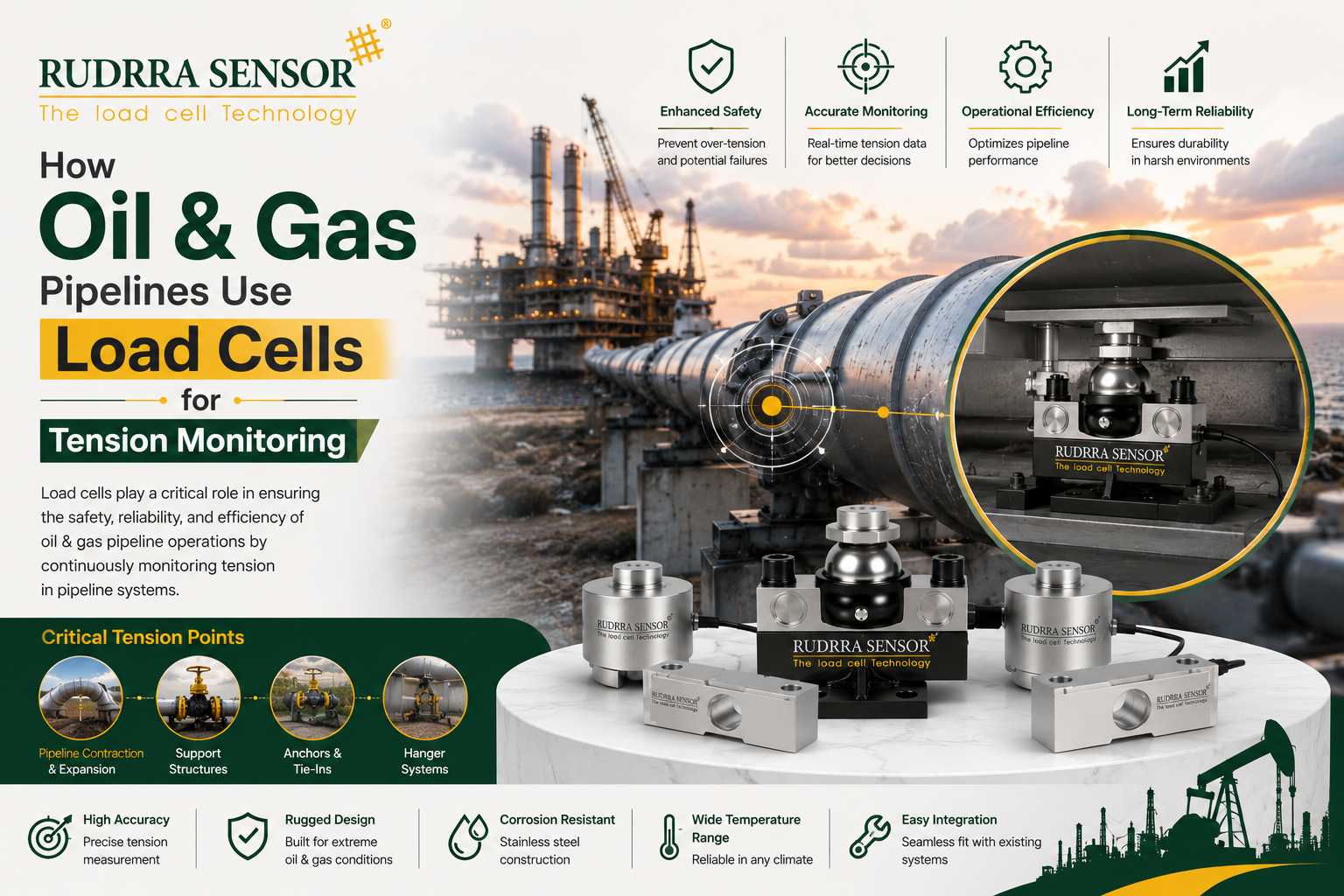
Introduction
Oil and gas pipelines are among the most consequential pieces of industrial infrastructure in the world — networks of steel and composite pipe carrying crude oil, refined products, and natural gas across continents, through deserts, mountains, rivers, seismic zones, and increasingly, deep offshore environments. A pipeline failure is never a minor event: it can mean environmental contamination, explosion risk, extended supply disruption, and regulatory and reputational consequences that play out over years. Much of the engineering effort that goes into pipeline design, construction, and operation exists specifically to prevent that failure — and a surprisingly large part of that effort comes down to managing one variable: mechanical tension and stress in the pipe itself.
Pipelines are not static, inert structures. They expand and contract with temperature swings, settle and shift with ground movement, experience internal pressure surges, and in many installations are deliberately held under controlled tension as part of their design — suspended pipeline crossings, offshore riser systems, and pipe-laying operations all depend on precisely managed tension to keep the pipe within its safe structural envelope. Load cells are the sensing technology that makes it possible to measure that tension accurately, continuously, and reliably, whether during the pipe-laying process itself, in a permanently instrumented suspension bridge crossing, or as part of an anchor and restraint system holding a pipeline segment in position against thermal and pressure-induced movement.
This blog is a deep, practical look at how load cells are used for tension monitoring across the oil and gas pipeline sector — from offshore pipe-laying vessels and riser tensioning systems, to onshore suspended crossings and anchor block monitoring, to pull-in and pipeline commissioning operations. We will cover why tension monitoring matters so much for pipeline integrity, the extreme technical trust factors this application demands given the safety and environmental stakes involved, real-world case studies, the standards and certifications that matter (including hazardous area classification, since pipeline environments are almost always potentially explosive atmospheres), and the common specification mistakes that can undermine an otherwise well-designed tension monitoring system.
At Rudrra Sensor, we understand that in oil and gas applications, a load cell is never simply a measurement convenience — it is frequently part of the safety case for the entire pipeline system. This article is written with that reality in mind, for engineers, integrity management teams, and procurement specialists who need to understand not just what a tension load cell does, but what genuinely matters when specifying one for this uniquely demanding sector.
It’s worth acknowledging upfront why this topic deserves such careful treatment compared to many other industrial load cell applications. In a factory weighing application, a measurement error typically produces a wrong number on a display, a slightly inaccurate billing record, or at worst a batch of product that fails quality control. In pipeline tension monitoring, a measurement error — or worse, a complete but undetected sensor failure — can mean an operation proceeds without the safety-critical feedback it depends on, at a moment when the physical consequences of getting tension wrong range from equipment damage to pipeline buckling to, in the most severe scenarios, structural failure with associated environmental and safety risk. This is not intended to be alarmist; it is simply the operating reality that shapes every specification decision covered in this article, and it is why the oil and gas sector’s own engineering culture treats instrumentation selection with a rigor that other industries sometimes reserve only for the primary process equipment itself.
Why Tension Monitoring Matters in Pipeline Operations
Thermal expansion and contraction create substantial axial forces
Steel pipelines carrying hot product, or simply exposed to significant seasonal or diurnal temperature swings, expand and contract along their length. A long, unrestrained run of pipe can experience movement in the range of many centimeters between temperature extremes, and where that movement is constrained — at anchor points, expansion loops, or fixed supports — the resulting axial force can reach very substantial magnitudes, often calculated in hundreds of tonnes of force for larger-diameter, thick-walled pipelines. Tension monitoring at these constrained points verifies that actual forces remain within the design envelope the pipeline’s structural engineering was based on, rather than relying purely on theoretical calculation.
Internal pressure generates additional axial and hoop stress
Beyond thermal effects, internal pressure itself generates both hoop stress (circumferential) and, particularly at bends, reducers, and closed ends, additional axial force on the pipe and its supporting structure. Pressure surges — from valve closures, pump start-stop events, or upset conditions — can transiently spike these forces well above steady-state operating levels, making dynamic, continuous tension monitoring more valuable than a single static design calculation for high-consequence sections of pipeline.
Suspended and elevated crossings depend entirely on correct tension
Where a pipeline crosses a river, ravine, road, or other obstacle via a suspended or elevated crossing — sometimes spanning hundreds of meters — the crossing’s structural integrity depends on the supporting cables or the pipe itself being held within a carefully engineered tension range. Too little tension and the span can sag excessively or develop unacceptable vibration under wind loading; too much tension risks exceeding the structural capacity of the cables, saddles, or the pipe wall itself. Load cells integrated into the suspension system provide the ongoing verification that the crossing remains within its safe operating envelope throughout its service life, which for major pipeline infrastructure can extend to several decades.
Offshore pipe-laying is entirely dependent on real-time tension control
During offshore pipeline installation, the pipe is fed off a lay vessel and lowered to the seabed under carefully controlled tension, managed by tensioner systems on the vessel that must react to the constantly changing catenary shape of the pipe as it descends through the water column, the vessel’s own movement from wave action, and water depth, which for deepwater developments can exceed 1,500 to 3,000 meters. Too little tension during lay risks the pipe buckling under its own weight in the free-span section between the vessel and the seabed touchdown point — a catastrophic failure mode known in the industry as pipeline buckling or “pipe walk” — while excessive tension can overstress the pipe wall or the tensioner equipment itself. Load cells integrated into the lay vessel’s tensioner system and, on some vessel types, into the stinger or ramp structure guiding the pipe off the vessel, provide the real-time feedback that makes controlled, safe pipe-laying possible at all.
Riser tension systems support the entire weight of offshore production risers
On offshore platforms and floating production facilities, risers — the vertical or near-vertical pipe sections connecting subsea wells or pipelines to surface production facilities — are frequently held under substantial top tension by dedicated riser tensioner systems, particularly on floating platforms where the riser must accommodate significant vessel motion while maintaining structural integrity. Load cells within these tensioner systems provide continuous verification that riser tension remains within the narrow operating window required to prevent both riser buckling (from insufficient tension) and excessive stress at the riser’s connection points (from excessive tension).
Anchor and restraint systems for buried and above-ground pipelines
Buried pipelines, particularly at points where they transition to above-ground sections, cross fault lines in seismically active regions, or connect to fixed equipment such as pump stations and valve manifolds, often incorporate engineered anchor blocks and restraint systems designed to manage the axial forces described above. Load cells integrated into these anchor systems, or into strain gauge-based monitoring on the pipe itself near these transition points, support both routine integrity monitoring and, in seismically active regions, post-event assessment of whether a pipeline segment has experienced forces beyond its design envelope following an earthquake.
The broader pipeline integrity management context
It’s worth situating tension monitoring within the broader discipline of pipeline integrity management, since load cells rarely operate as a standalone measurement system in isolation. Modern pipeline operators typically run comprehensive integrity management programs that combine multiple monitoring techniques — in-line inspection (“smart pigging”) for wall thickness and corrosion, cathodic protection monitoring for external corrosion control, geotechnical monitoring for ground movement in unstable terrain, and mechanical load monitoring including the tension measurement applications covered in this article — into an integrated picture of pipeline condition. Tension monitoring data is most valuable not in isolation but when correlated with this broader dataset, since a tension reading trending outside its normal historical range can be an early indicator worth investigating alongside other integrity data, well before it would trigger an isolated alarm threshold on its own.
Where Load Cells Are Used Across the Pipeline Lifecycle
Offshore pipe-laying vessel tensioner systems
As described above, lay vessel tensioners — the large caterpillar-track or roller-based systems that grip and control the pipe as it feeds off the vessel — incorporate load cells to provide the real-time tension feedback that vessel dynamic positioning and lay control systems depend on to maintain safe, controlled installation throughout the laying operation, which for a major offshore pipeline project can continue around the clock for many weeks or months.
Riser tensioner systems on floating production facilities
Hydraulic or pneumatic riser tensioner units, supporting production risers, drilling risers, and export risers on floating platforms, incorporate load cells to continuously monitor top tension, feeding data into the platform’s riser management system to ensure tension stays within the operating envelope across the full range of platform motion the facility experiences from wave, wind, and current loading.
Pipeline pull-in and shore approach operations
During pipeline installation at shore approaches — where an offshore pipeline is pulled through a pre-drilled or trenched shore crossing to connect with onshore infrastructure — winch and pulling systems use load cells to monitor pull force in real time, ensuring the pipe is not subjected to excessive tension that could damage the pipe wall or its coating during this mechanically demanding installation phase.
Suspended and cable-supported pipeline crossings
As discussed above, load cells integrated into the suspension cables, saddles, or anchor points of elevated pipeline crossings provide ongoing verification of tension distribution across the crossing, often as part of a broader structural health monitoring program for major crossings that also includes displacement, vibration, and strain monitoring on the pipe and supporting structure itself.
Pipeline testing and commissioning
Before a new pipeline section enters service, hydrostatic testing and other commissioning activities may involve controlled tensioning or restraint force verification, particularly at anchor points and expansion joints, to confirm the as-built structure behaves as designed under representative load conditions before the pipeline is placed into full operational service.
Anchor block and restraint monitoring during operation
For pipelines where thermal or pressure-induced axial force is managed through engineered anchor blocks, permanently installed load cells or strain-based monitoring systems provide ongoing integrity data throughout the pipeline’s operational life, supporting both routine integrity management programs and, where applicable, regulatory reporting requirements.
Pipeline repair and tie-in operations
During in-service pipeline repair, tie-in of new sections, or hot-tap operations, temporary tensioning and alignment equipment used to bring pipe sections into position for welding or mechanical connection frequently incorporates load cells to verify that the pipe is not being forced into alignment under excessive stress, which could compromise the integrity of the completed weld or connection.
Pipeline decommissioning and recovery operations
At the other end of the pipeline lifecycle, decommissioning projects that involve recovering sections of pipe from the seabed or extracting buried pipe sections also depend on controlled tension management, using load cells to monitor pulling and lifting forces during recovery operations, ensuring that aged, potentially corroded, or structurally weakened pipe is not subjected to forces beyond what its remaining structural capacity can safely tolerate during the decommissioning process itself.
How Pipeline Tension Load Cells Differ From Standard Industrial Load Cells
Hazardous area certification is almost always mandatory
Because pipeline environments routinely involve the potential presence of flammable hydrocarbon vapors, load cells used in and around pipeline facilities — particularly at wellheads, pump stations, offshore platforms, and any enclosed or semi-enclosed processing area — typically require certification for use in hazardous (explosive) atmospheres, commonly referenced against ATEX classification in Europe-influenced markets, IECEx internationally, or equivalent national frameworks elsewhere. This is a fundamentally different design and certification requirement compared to a standard industrial load cell, affecting everything from the sensor’s electrical design (intrinsically safe or explosion-proof/flameproof construction) to its documentation and marking requirements.
Extreme environmental exposure, both onshore and offshore
Pipeline infrastructure spans an extraordinary range of environmental conditions — desert heat, Arctic cold, high-humidity tropical environments, and for offshore applications, direct and continuous exposure to seawater, salt spray, and the corrosive marine atmosphere. Load cells specified for pipeline tension monitoring must be engineered for the specific environmental extreme of their installation location, typically requiring wide temperature compensation ranges, high IP sealing ratings, and corrosion-resistant materials such as marine-grade stainless steel for offshore applications.
Very high capacity ranges for major infrastructure
As discussed in the introduction, axial forces on major pipeline infrastructure — particularly large-diameter, thick-walled pipe under significant thermal or pressure loading, or riser tensioner systems supporting substantial platform equipment weight — can reach very high capacities, often requiring load cells rated well into the hundreds of tonnes, sometimes over a thousand tonnes for major offshore riser and lay vessel tensioner applications.
Long-term reliability with minimal maintenance access
Many pipeline tension monitoring points, particularly buried anchor systems, remote onshore crossings, and subsea installations, are extremely difficult or expensive to access for maintenance once installed. This drives a strong design preference for load cells with proven long-term reliability, minimal maintenance requirements, and — where budget allows — a degree of self-diagnostic capability that can flag developing issues before an outright sensor failure occurs in a location that might not be revisited for years.
Redundancy and fail-safe design philosophy
Given the safety-critical nature of many pipeline tension monitoring applications, system designs frequently incorporate redundant load cells or sensor channels, along with fail-safe logic that ensures a sensor failure produces a clear fault indication rather than a silently incorrect reading — a design philosophy consistent with broader process safety engineering practice in the oil and gas sector.
Integration with process safety and control systems
Pipeline tension data frequently feeds directly into safety instrumented systems (SIS) and process control systems governing vessel dynamic positioning, riser tensioner operation, or emergency shutdown logic, meaning the load cell’s output signal, response time, and reliability characteristics must meet the broader system’s safety integrity requirements, not just general measurement accuracy expectations.
A Practical Specification Checklist
Given the safety-critical, highly regulated nature of oil and gas pipeline applications, working through a structured specification checklist before approaching a supplier is particularly important:
- Application type and location in the pipeline lifecycle — pipe-laying tensioner, riser tensioner, suspended crossing, anchor monitoring, pull-in operation, or another application.
- Expected tension range, including both normal operating tension and credible worst-case dynamic or transient scenarios.
- Hazardous area classification applicable to the installation location, including the specific zone/division classification and gas group where relevant.
- Environmental exposure, including temperature range, offshore/marine exposure, burial (if applicable), and any specific chemical exposure relevant to the location.
- Required accuracy and response time, driven by whether the application involves real-time safety-critical control (such as lay vessel tensioning) or periodic integrity monitoring.
- Redundancy and fail-safe requirements, based on the safety criticality of the specific monitoring point and any applicable safety integrity level requirements.
- Signal output and integration requirements, matched to the specific control, safety, or monitoring system the load cell will feed into.
- Access and maintenance constraints, particularly for remote, buried, or subsea installations where future maintenance access will be difficult or impossible.
- Applicable regulatory and certification requirements, including hazardous area certification standards and any pipeline-specific regulatory framework relevant to the project’s jurisdiction.
- Calibration and documentation requirements, particularly important given how directly pipeline integrity data can be tied to regulatory compliance and safety case documentation.
Trust Factors: Technical Benchmarks for Pipeline Tension Load Cells
| Trust Factor | Why It Matters | Typical Benchmark |
| Hazardous area certification | Required for use in flammable atmosphere zones | ATEX/IECEx certification matched to the specific zone classification |
| Capacity range | Must match extreme axial forces on major infrastructure | Ranges from tens of tonnes to 1,000+ tonnes depending on application |
| Corrosion resistance | Withstands marine, offshore, or buried environments | Marine-grade stainless steel or equivalent corrosion protection |
| IP/environmental sealing | Protects against seawater, moisture, burial exposure | IP68 minimum for offshore/subsea and buried applications |
| Temperature range | Withstands extreme onshore and offshore climates | Wide compensated range matched to the specific installation region |
| Overload capacity | Protects against pressure surge and dynamic transients | Mechanical overload rating well above normal operating tension |
| Redundancy | Ensures continued monitoring if one sensor channel fails | Dual or triple redundant load cells for safety-critical points |
| Response time | Supports real-time control in dynamic applications | Fast enough to track lay vessel/riser tensioner dynamic conditions |
| Long-term drift/creep performance | Ensures accuracy over extended, low-maintenance service life | Minimal long-term drift specification for multi-year unattended service |
| Calibration traceability | Confirms measurement accuracy is verifiable and auditable | Certificate traceable to a recognized national/international standard |
Why hazardous area certification is the defining trust factor in this sector
Unlike most other industries covered elsewhere in this series, hazardous area certification is not an optional enhancement for pipeline load cells — it is very often a legal and regulatory prerequisite for the sensor to be installed at all in the majority of pipeline-associated locations. Certification frameworks classify hazardous locations into zones or divisions based on the likelihood and duration of a flammable atmosphere being present, and load cells must be certified to a protection method (such as intrinsic safety, flameproof/explosion-proof enclosure, or increased safety) appropriate to the specific zone classification of their installation location. A load cell without correct, documented hazardous area certification is not simply a lower-quality choice in this context — it can represent a genuine regulatory non-compliance and safety hazard, making certification verification one of the very first things to confirm with any supplier, not a detail to be addressed after commercial terms are agreed.
Why redundancy matters more here than in most other sectors
Given how directly pipeline tension data can feed into safety-critical control and shutdown logic — particularly for offshore lay vessel and riser tensioner systems, where a sudden, undetected loss of accurate tension data during an active operation could have severe consequences — redundant sensor architectures are far more common in this sector than in general industrial weighing applications. This typically means installing multiple load cells at critical monitoring points, with voting or comparison logic in the associated control system that can identify a faulty sensor and maintain safe operation (or trigger a controlled, safe shutdown) even if one sensor channel fails.
Relevant standards and regulatory frameworks
- ATEX (European hazardous area directive) and IECEx (International Electrotechnical Commission scheme for explosive atmospheres) are the most widely referenced hazardous area certification frameworks internationally, and pipeline projects operating across multiple jurisdictions frequently need equipment certified to whichever framework, or combination of frameworks, applies to the specific project locations.
- API (American Petroleum Institute) standards, while primarily focused on broader pipeline design, construction, and integrity management practice rather than load cell specifications directly, provide important context for the engineering framework within which tension monitoring systems are typically specified and documented on oil and gas projects.
- DNV and classification society standards are particularly relevant for offshore pipe-laying vessels and riser tensioner systems, where marine classification requirements intersect with the equipment’s process safety certification.
- ISO 9001 manufacturing quality certification and ISO/IEC 17025 calibration traceability remain relevant general quality and metrology benchmarks, applicable here as in other load cell application sectors, though typically supplemented by the sector-specific hazardous area and integrity management frameworks described above.
Case Study 1: Preventing Overstress During an Offshore Pipe-Lay Operation
The situation: An offshore pipeline installation contractor was laying a large-diameter export pipeline in deepwater conditions, where the free-span section of pipe between the lay vessel and the seabed touchdown point is particularly vulnerable to buckling if tension control is not maintained precisely within the calculated safe operating window throughout the entire laying operation.
The challenge: The vessel’s existing tensioner system used load cells that had not been recalibrated to reflect a recent tensioner mechanical refurbishment, resulting in a tension reading that, while internally consistent, had drifted from true calibrated accuracy by a margin that, while small in percentage terms, represented a meaningful absolute tension difference given the very high forces involved in the operation — a discrepancy identified only through a pre-campaign independent verification check against reference calibration equipment, a standard practice for major lay campaigns.
The solution: The affected load cells were removed, sent for full recalibration and inspection, and reinstalled with updated calibration documentation before the lay campaign proceeded, alongside a revised pre-campaign verification protocol requiring independent tension reference checks at defined intervals throughout the multi-week campaign rather than relying solely on the initial pre-campaign calibration.
The outcome: The corrected calibration allowed the lay campaign to proceed with confidence that tensioner readings accurately reflected true pipe tension throughout the operation, avoiding the risk of the vessel’s control system operating on a systematically offset tension figure during a safety-critical, high-consequence operation. The revised verification protocol was subsequently adopted as standard practice across the contractor’s fleet for future campaigns.
Lessons for similar projects: This case underscores a theme relevant across every high-consequence application in this article: a load cell’s calibration accuracy cannot be assumed to remain valid indefinitely, particularly following any mechanical work on the system it’s integrated into, and independent verification checks — not just reliance on the sensor’s original factory calibration — are a critical safeguard for safety-critical, high-value operations where even a small percentage calibration error translates into a significant absolute force discrepancy. It’s also worth noting that this issue was caught not by the tensioner system itself flagging an anomaly, but through a disciplined, independent pre-campaign verification protocol — a reminder that a control system trusting its own sensor without external verification cannot, by definition, catch a calibration drift in that same sensor, which is precisely why independent reference checks remain an essential safeguard even in otherwise well-instrumented systems.
Case Study 2: Redundant Riser Tension Monitoring on a Floating Production Platform
The situation: An operator of a floating production facility needed to upgrade the riser tensioner monitoring system on a production riser as part of a broader platform integrity and safety systems modernization program, replacing aging single-channel load cell instrumentation that had been identified as a single point of failure risk during a facility-wide safety review.
The challenge: The existing system’s single load cell per riser tensioner meant that any individual sensor failure would result in a complete loss of tension monitoring for that riser until the sensor could be replaced — a maintenance activity requiring planned platform downtime access to the tensioner system, and in the interim, the riser would be operating without the real-time tension verification the platform’s safety case assumed was continuously available.
The solution: The tensioner monitoring system was upgraded to a redundant dual load cell configuration per riser, with each load cell independently certified for the platform’s hazardous area classification and wired into separate, independently monitored channels feeding the platform’s riser management system. Voting logic was implemented so that a discrepancy between the two channels beyond a defined threshold would trigger an alert for investigation, while continued reliable operation of at least one channel would maintain full tension monitoring capability without requiring immediate emergency intervention.
The outcome: The upgraded system eliminated the single point of failure risk identified in the original safety review, and within the following operational period, the voting logic successfully flagged a developing fault in one sensor channel well before it would have resulted in a complete loss of monitoring under the old single-channel design, allowing planned, non-emergency replacement to be scheduled during a routine maintenance window rather than requiring an unplanned response.
Lessons for similar projects: This case illustrates the practical value of redundant sensor architecture beyond the theoretical safety case justification: the redundant system did not just provide a backup in case of failure, it provided early warning of a developing problem that the single-channel system would have missed entirely, converting an unplanned emergency response into a planned maintenance activity — a meaningful operational and safety benefit beyond the redundancy’s original design intent.
Case Study 3: Suspended Crossing Tension Verification After a Seismic Event
The situation: A pipeline operator responsible for a major suspended river crossing in a seismically active region needed to rapidly assess the crossing’s structural condition following a moderate regional earthquake, as part of standard post-seismic-event integrity procedures required under the operator’s safety management system.
The challenge: Without permanently installed tension monitoring instrumentation, assessing whether the crossing’s suspension cables had experienced forces beyond their design envelope during the seismic event would have required a time-consuming manual inspection and engineering assessment process, delaying the operator’s ability to confirm the crossing’s continued safe operation or identify the need for load restriction pending further investigation.
The solution: Fortunately, the crossing had been retrofitted several years earlier with permanently installed load cells at the suspension cable anchor points, feeding continuous tension data into the operator’s integrity monitoring system. Following the seismic event, the operator’s engineering team was able to immediately review the load cell data logs covering the event itself, confirming that peak tension values recorded during the earthquake remained within the crossing’s established safe operating envelope.
The outcome: The immediate availability of quantitative tension data allowed the operator to confirm the crossing’s continued safe operational status within hours of the seismic event, rather than the days that a purely manual inspection-based assessment might have required, minimizing unnecessary supply disruption while still meeting the rigorous safety verification standard the operator’s integrity management program required.
Lessons for similar projects: This case demonstrates a value proposition for permanent tension monitoring instrumentation that extends well beyond routine operational monitoring: having continuous, time-stamped tension data available during and after an unusual event — whether seismic activity, an extreme weather event, or an unusual operational upset — provides a fast, quantitative basis for safety assessment that a purely reactive, inspection-based approach cannot match, particularly for infrastructure in regions prone to the kind of episodic events that make rapid, evidence-based safety assessment operationally valuable.
Case Study 4: Anchor Block Load Monitoring on a Long-Distance Onshore Pipeline
The situation: An operator of a long-distance onshore crude oil pipeline, running through a region with significant seasonal temperature variation and several sections of unstable, slowly shifting ground, wanted to improve its integrity management program’s ability to detect abnormal axial loading at engineered anchor points along the route before it could contribute to a more serious mechanical issue.
The challenge: The pipeline’s existing integrity management program relied primarily on periodic visual inspection and in-line inspection tools focused on wall thickness and corrosion, neither of which directly measured the axial tension being carried by the pipeline’s anchor block restraint systems — meaning any abnormal loading trend developing at these points, whether from unusually severe seasonal thermal cycling or gradual ground movement, would not be directly visible through the operator’s existing monitoring toolkit until it had progressed to a point detectable through other means, such as visible pipe distress or a mechanical issue at the anchor structure itself.
The solution: Load cells rated for long-term, low-maintenance outdoor service were installed at a number of the pipeline’s most consequential anchor block locations — selected based on a risk assessment prioritizing sections with the most severe combination of thermal cycling exposure and ground stability concerns — with data transmitted back to the operator’s central integrity monitoring system for ongoing trend analysis alongside the pipeline’s other integrity datasets.
The outcome: Within the first full annual thermal cycle of operation, the monitoring system provided the operator’s integrity engineering team with, for the first time, direct quantitative confirmation of how actual anchor loading tracked against the theoretical thermal expansion calculations used in the original pipeline design — data that was subsequently used to refine the operator’s broader integrity risk models for anchor points across the wider pipeline network, not just the specific instrumented locations. At one location, seasonal load trends were found to be tracking slightly outside the originally modeled range, prompting a focused engineering review that identified a need for minor remedial ground stabilization work well ahead of it becoming a more significant structural concern.
Lessons for similar projects: This case illustrates how direct measurement can validate — or, as it did in this instance, meaningfully refine — theoretical design assumptions that may otherwise go unchecked for the entire operational life of a pipeline. Anchor point design calculations are necessarily based on assumptions about soil behavior, thermal cycling, and ground stability that can diverge from actual site conditions over time, and direct load measurement provides the kind of real-world verification that purely calculation-based integrity assessment cannot offer on its own.
Common Specification and Installation Mistakes to Avoid
Given the safety-critical, highly regulated nature of oil and gas pipeline tension monitoring, specification and installation mistakes in this sector carry unusually significant consequences. The following are the issues most frequently encountered in the field.
Underestimating or omitting hazardous area certification requirements
As discussed extensively above, installing a load cell without correct, documented hazardous area certification for its specific installation zone is not a minor specification oversight — it represents a genuine regulatory and safety risk. This should be the first item confirmed in any pipeline load cell specification, not an afterthought addressed once other technical details are settled.
Assuming factory calibration remains valid indefinitely
As Case Study 1 demonstrated, calibration accuracy cannot be assumed to hold indefinitely, particularly following mechanical work on the system a load cell is integrated into. Safety-critical, high-consequence applications warrant independent verification checks at defined intervals, not sole reliance on original factory calibration documentation.
Treating single-channel monitoring as adequate for safety-critical points
As Case Study 2 demonstrated, single-channel load cell monitoring creates a single point of failure risk for safety-critical applications, and redundant sensor architecture with appropriate voting or comparison logic should be considered standard practice for high-consequence monitoring points rather than an optional enhancement.
Underestimating environmental and corrosion protection requirements
Offshore and marine pipeline applications in particular demand corrosion protection and environmental sealing well beyond what a standard onshore industrial load cell provides. Specifying environmental protection matched only to a generic “outdoor” assumption, rather than the genuine marine or offshore exposure the sensor will actually face, risks premature failure in exactly the applications where reliable, long-term monitoring matters most.
Failing to plan for the realistic inaccessibility of remote monitoring points
Buried anchor systems, remote onshore crossings, and subsea installations are often extremely difficult and expensive to access once installed. Specifying a load cell without adequate consideration of long-term reliability, self-diagnostic capability, and realistic maintenance access constraints can lead to a monitoring system that becomes effectively unmaintainable, or requires disproportionately expensive intervention to service, well before the end of its intended design life.
Insufficient integration planning with safety instrumented systems
Where tension data feeds into safety instrumented systems or emergency shutdown logic, the load cell’s response time, reliability, and failure mode characteristics must be properly integrated into the broader system’s safety case, including formal safety integrity level (SIL) assessment where applicable — a specialized engineering process that goes well beyond simply connecting a sensor’s output to a control system input.
Overlooking documentation and traceability requirements for regulatory compliance
Given how directly pipeline tension monitoring data can be tied to regulatory compliance and safety case documentation, calibration records, certification documentation, and installation records should be maintained with the same rigor as other safety-critical pipeline integrity documentation — a requirement that is sometimes underestimated relative to the attention given to the sensor’s technical specification itself.
Underestimating dynamic response requirements for real-time control applications
For applications such as lay vessel tensioning and riser tensioner control, where tension data feeds directly into real-time operational control decisions, a load cell with inadequate dynamic response characteristics can introduce lag or noise into the control loop that undermines the precision the operation depends on — a consideration distinct from, and in addition to, the sensor’s static accuracy specification.
The common thread: treating instrumentation as part of the safety case, not an accessory to it
Reviewing this list, the pattern that emerges is consistent with the broader theme of this article: every one of these mistakes stems from treating a pipeline tension load cell as a general-purpose measurement accessory rather than as a genuine component of the pipeline’s safety and integrity case. The oil and gas sector’s own engineering culture — built around formal hazard identification, safety integrity level assessment, and rigorous documentation — already provides the right framework for avoiding these mistakes; the specification and installation of tension monitoring load cells simply needs to be brought fully within that same framework, rather than being treated as a lower-stakes instrumentation decision separate from the broader engineering and safety process governing the rest of the project.
Cost vs. Value: Justifying Investment in Pipeline-Grade Tension Monitoring
Given the certification, redundancy, and environmental protection requirements described throughout this article, pipeline-grade tension load cells represent a significant investment relative to general industrial sensors. The value case, however, is unusually strong in this sector given the consequences at stake:
- Catastrophic failure avoidance: As Case Study 1 illustrated, accurate tension monitoring during high-consequence operations such as offshore pipe-laying directly reduces the risk of pipeline buckling or overstress failure, consequences that carry costs — financial, environmental, and reputational — that dwarf the cost of properly specified monitoring equipment many times over.
- Reduced unplanned downtime through early fault detection: As Case Study 2 demonstrated, redundant monitoring architectures can convert an unplanned emergency sensor failure into a planned maintenance activity, avoiding the operational disruption and cost premium associated with emergency intervention on offshore or remote infrastructure.
- Faster, evidence-based safety assessment after unusual events: As Case Study 3 demonstrated, permanently instrumented monitoring provides a fast, quantitative basis for safety verification following seismic events, extreme weather, or operational upsets, reducing both unnecessary supply disruption and the risk of resuming operation without adequate verification.
- Validation and refinement of design assumptions over the pipeline’s operating life: As Case Study 4 demonstrated, direct load measurement at anchor points can validate or meaningfully refine theoretical thermal and geotechnical design assumptions, supporting more accurate integrity risk models across an operator’s wider network, not just the specific instrumented locations.
- Regulatory compliance and audit defensibility: Properly documented, traceable tension monitoring data strengthens an operator’s position in regulatory audits and, where relevant, incident investigations, reducing both compliance risk and the potential cost of regulatory enforcement action.
- Extended safe operating life for major infrastructure: Suspended crossings, riser systems, and other major pipeline infrastructure represent very substantial capital investments with design lives extending to several decades; properly specified, long-term reliable tension monitoring supports the integrity management practices needed to safely achieve that full design life.
Framing pipeline tension monitoring investment in terms of risk reduction and total lifecycle value, rather than simple equipment cost comparison, reflects how this sector’s own safety and integrity management frameworks already approach capital investment decisions more broadly.
Choosing the Right Supplier for Pipeline Tension Monitoring Load Cells
Given the highly specialized certification, environmental, and safety-integration requirements involved, supplier selection is particularly consequential for pipeline tension monitoring projects:
- Demonstrated hazardous area certification expertise, including the ability to supply documentation appropriate to the specific certification framework and zone classification your project requires
- Experience with offshore and marine environmental requirements, where relevant, including corrosion protection and sealing appropriate to genuine subsea or offshore atmospheric exposure
- Support for redundant sensor architectures and safety system integration, including willingness to engage with your project’s broader safety instrumented system design process where applicable
- Robust, traceable calibration and documentation practices, given how directly this data can be tied to regulatory compliance and safety case documentation
- A track record specifically within oil and gas pipeline applications, since the failure modes, certification requirements, and safety culture in this sector differ meaningfully from general industrial weighing or force measurement applications
- Willingness to support long-term reliability and maintenance planning discussions, particularly for remote or difficult-to-access monitoring points where a straightforward “sell and ship” transaction is inadequate for the realistic long-term support the application requires
At Rudrra Sensor, we recognize that pipeline tension monitoring sits within a broader safety and integrity management framework that goes well beyond the sensor itself, and we work with engineering and integrity management teams to understand the specific certification, environmental, and system integration requirements each project demands before recommending a solution.
Emerging Trends in Pipeline Tension Monitoring
Greater adoption of continuous, permanently installed monitoring
As illustrated in Case Study 3, the value of permanent, continuous tension monitoring — rather than periodic manual inspection — is increasingly recognized industry-wide, particularly for major infrastructure in seismically active regions or other locations prone to episodic events that warrant rapid, evidence-based safety assessment capability.
Integration with digital twin and predictive integrity management platforms
Pipeline operators are increasingly integrating tension and other structural monitoring data into broader digital twin and predictive integrity management platforms, correlating real-time sensor data with engineering models to support more proactive, data-driven integrity management decisions than periodic inspection-based approaches alone can achieve.
Wireless and low-power monitoring for remote installations
For remote onshore crossings and other locations where running permanent power and signal cabling is impractical or prohibitively expensive, wireless, low-power, and energy-harvesting load cell designs are increasingly being explored to extend continuous monitoring capability to locations that would previously have relied solely on periodic manual inspection.
Enhanced self-diagnostic capability for unattended, long-service-life installations
Given the long service life and difficult access characteristic of many pipeline monitoring points, there is growing interest in load cells with enhanced onboard diagnostic capability — reporting not just tension data but also sensor health indicators — supporting the kind of proactive, planned maintenance approach illustrated in Case Study 2, rather than relying solely on complete sensor failure as the trigger for maintenance intervention.
Tighter integration between marine/offshore classification and process safety certification
As offshore developments move into increasingly challenging deepwater and harsh environment locations, there is a continuing trend toward closer integration between marine classification society requirements and process safety hazardous area certification frameworks, reflecting the reality that offshore pipeline tension monitoring equipment must satisfy both regulatory domains simultaneously rather than treating them as separate, sequential compliance exercises.
Growing use of tension data in broader climate and ground movement resilience planning
As illustrated in Case Study 4, tension and load monitoring data at anchor points is increasingly being used not just for point-in-time integrity verification but as an input into longer-term climate resilience and ground stability planning, particularly relevant as operators reassess design assumptions in light of more variable seasonal temperature patterns and, in some regions, changing ground stability conditions over a pipeline’s multi-decade operating life.
Frequently Asked Questions (FAQs)
Q1: Why is hazardous area certification so central to pipeline load cell selection?
Because pipeline environments routinely involve the potential presence of flammable hydrocarbon vapors, load cells installed in or near these areas typically must be certified to a recognized hazardous area protection method appropriate to the specific zone classification, making this a regulatory and safety prerequisite rather than an optional specification enhancement.
Q2: Do all pipeline tension monitoring applications require redundant load cells?
Not necessarily — redundancy requirements should be based on a proper safety and risk assessment of the specific monitoring point’s criticality, but for applications directly feeding safety-critical control or shutdown logic, such as riser tensioner systems on floating platforms, redundant architecture is increasingly considered standard practice rather than an optional enhancement.
Q3: How is tension monitoring different between onshore and offshore pipeline applications?
The underlying measurement principle is the same, but offshore applications typically demand significantly more robust environmental protection (marine-grade corrosion resistance, higher IP sealing ratings), often higher capacity ranges given the forces involved in deepwater pipe-laying and riser tensioning, and closer integration with marine classification society requirements alongside standard hazardous area certification.
Q4: Can load cell tension data really support post-earthquake or post-event safety assessment, as in Case Study 3?
Yes — permanently installed tension monitoring with data logging capability allows an operator to review actual recorded forces experienced during a specific event against the structure’s established safe operating envelope, providing a fast, quantitative basis for safety assessment that a purely visual, inspection-based approach cannot match on its own.
Q5: Is tension monitoring only relevant for major offshore infrastructure, or does it apply to smaller onshore pipelines too?
While the highest-capacity, most complex applications (offshore lay vessels, floating platform risers) tend to get the most attention, as Case Study 4 shows, onshore anchor block monitoring on a conventional long-distance pipeline is equally valuable, and often more cost-effective to implement, since it typically involves lower capacity ranges and less demanding environmental protection than offshore applications while still delivering meaningful integrity management value.
Conclusion
Oil and gas pipeline infrastructure operates under some of the most demanding combinations of technical, environmental, and regulatory requirements found anywhere in industrial load cell applications — extreme capacity ranges, mandatory hazardous area certification, marine and offshore environmental exposure, and consequences of failure that extend to genuine safety and environmental risk rather than simply operational inconvenience. The four case studies above — a calibration verification catching a drift risk before a high-consequence offshore lay campaign, a redundant riser tensioner system converting an emergency failure into planned maintenance, permanently installed crossing monitoring enabling rapid post-seismic safety assessment, and onshore anchor block monitoring refining an operator’s integrity risk models — all point to a consistent theme: properly specified, genuinely certified, and rigorously maintained tension monitoring is not a peripheral technical detail in pipeline operations, but a direct and meaningful contributor to the safety case the entire industry operates under.
If your organization is specifying tension monitoring for pipeline infrastructure — whether for an active pipe-laying campaign, a permanent riser tensioner system, or a suspended crossing integrity monitoring program — the questions worth asking align closely with the themes running throughout this article: is the load cell genuinely certified for the hazardous area classification of its installation location, not just generally described as suitable? Is the environmental protection matched to the real exposure the sensor will face, particularly for offshore or marine applications? Does the monitoring architecture provide the redundancy appropriate to the point’s actual safety criticality? And can your supplier back all of this up with genuine oil and gas sector experience and fully traceable documentation, not just a relabeled industrial product?
At Rudrra Sensor, we approach every pipeline tension monitoring project with these questions front and center, because in this sector, getting tension measurement right is inseparable from getting pipeline safety right.
Need a tension monitoring solution engineered for your pipeline application? Get in touch with the Rudrra Sensor engineering team to discuss your capacity range, hazardous area classification, and environmental requirements, and we’ll help you specify a system built for the genuine demands of oil and gas pipeline operation.